Allen-Bradley 1756-OF8 Retrofit-Ready Analog Output Module for ControlLogix Control Systems
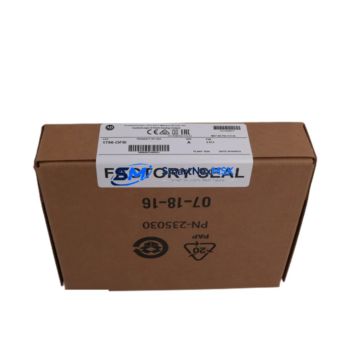
The Allen-Bradley 1756-OF8 is an 8-channel analog output module designed for the ControlLogix platform, delivering ±10 VDC or 4–20 mA output signals across all channels. As legacy ControlLogix installations age and original spare parts become increasingly difficult to source, the 1756-OF8 serves as a direct retrofit solution for facilities operating 1756-series backplanes — enabling smooth migration from discontinued configurations without requiring controller replacement or full panel redesign.
SMARTNEXMSK maintains verified stock of the 1756-OF8 for immediate dispatch, supporting maintenance teams, system integrators, and OEM rebuild projects that require a reliable, tested replacement with a 12-month warranty. Each unit undergoes pre-shipment functional verification to confirm channel output accuracy, backplane communication integrity, and module identity recognition within the ControlLogix chassis.
Upgrade Compatibility Table
| Parameter | Details |
|---|---|
| Compatible Platform | ControlLogix 1756 Series (all chassis sizes) |
| Backplane Interface | 1756 ControlLogix backplane (1756-A4, 1756-A7, 1756-A10, 1756-A13, 1756-A17) |
| Output Channels | 8 channels, individually configurable |
| Output Signal Types | ±10 VDC voltage / 4–20 mA current (per channel) |
| Communication Protocol | ControlNet / Ethernet/IP via 1756-ENBT, 1756-EN2T, or 1756-CN2 bridge modules |
| Replacement Candidates | 1756-OF8 (earlier firmware revisions), 1756-OF6VI, 1756-OF6CI (partial channel reduction) |
| Installation Requirement | Standard 1756 module slot; no additional mounting hardware required |
| Wiring Compatibility | Compatible with existing RTB (Removable Terminal Block) wiring; verify RTB model 1756-TBCH or 1756-TBS6H |
| Commissioning Note | Module tag re-mapping required in Studio 5000 / RSLogix 5000 if slot address changes |
| Warranty | 12 months from date of shipment |
Retrofit Planning for Existing Automation Systems
When integrating the 1756-OF8 into an existing ControlLogix system, the retrofit process typically begins with a full audit of the current chassis configuration. Engineers should document the slot assignments of all installed modules — including the 1756-L71 or 1756-L83E controller, any 1756-EN2T Ethernet/IP communication modules, and co-resident I/O modules such as the 1756-IF16 analog input or 1756-OB16E digital output — before removing the failed or discontinued unit.
Power budget verification is a critical pre-installation step. The 1756-OF8 draws current from the 1756-PA75 or 1756-PB75 power supply via the backplane. Confirm that the total chassis current draw — including the controller, communication modules, and all I/O — does not exceed the rated output of the installed power supply. If the existing supply is marginal, consider upgrading to the 1756-PA75R redundant power supply before proceeding.
Terminal block wiring should be mapped against the original I/O configuration printout. The 1756-OF8 uses a removable terminal block (RTB), typically the 1756-TBCH or 1756-TBS6H, which allows field wiring to be disconnected from the module without disturbing individual conductors. This significantly reduces downtime during hot-swap procedures in non-redundant systems. Verify that each analog output channel’s field device — including control valves, variable frequency drives, and positioners — is correctly mapped to the corresponding channel tag in the controller program.
For systems communicating over ControlNet, the 1756-CN2 or 1756-CNB module must be verified for scheduled connection capacity. Adding or replacing an analog output module may require updating the ControlNet network schedule using RSNetWorx for ControlNet. In Ethernet/IP-based architectures using the 1756-EN2T, no network reschedule is required, but the module’s connection path in the I/O tree must be confirmed in Studio 5000 Logix Designer.
HMI screen updates may be necessary if the original 1756-OF8 tags were renamed or if the replacement module occupies a different chassis slot. Verify all PanelView Plus or FactoryTalk View SE screens that reference analog output tags to ensure display accuracy after the swap. Program logic referencing output scaling, engineering unit conversion, and alarm limits should be reviewed and re-downloaded to the 1756-L series controller after module replacement.
Downtime Control During System Migration
Minimizing unplanned downtime during a ControlLogix analog output module replacement requires a structured pre-outage preparation protocol. Before the maintenance window opens, the engineering team should export the current controller program from Studio 5000 and archive it to a secure location. This preserves the original ladder logic, function block diagrams, and structured text routines — including all output scaling parameters and interlock conditions tied to the 1756-OF8 channels.
Where process conditions allow, place the affected analog output channels in manual mode at the DCS or SCADA level before initiating the physical swap. This prevents uncontrolled output transitions from propagating to field devices such as control valves or drives during the module removal interval. If the system uses a 1756-RM2 redundancy module pair, the switchover to the secondary controller can be triggered prior to the swap, allowing the primary chassis to be serviced without interrupting the control loop.
After installing the replacement 1756-OF8, perform a module identity check in Studio 5000 to confirm the firmware revision is compatible with the project file. If a firmware mismatch is detected, use ControlFLASH to update the module firmware before going online. Re-establish the I/O connection, verify channel output values against the process setpoints, and confirm that all analog output tags are updating correctly in the controller data table before returning the system to automatic control. Document the completed swap in the site maintenance log, including the module serial number, slot position, and post-commissioning test results.
Retrofit Support FAQ
Q1: Is the 1756-OF8 a direct drop-in replacement for an older revision of the same module?
Yes. The 1756-OF8 is backward compatible across all ControlLogix chassis generations. The module uses the same backplane connector and RTB footprint as earlier revisions. However, if the firmware revision of the replacement unit differs from the original, a firmware update via ControlFLASH may be required to match the project’s module definition in Studio 5000.
Q2: What wiring checks are required before powering up the replacement module?
Verify that the RTB (1756-TBCH or 1756-TBS6H) is correctly seated and that all field wiring terminations are tight and correctly mapped to the channel assignments documented in the original I/O schedule. Confirm that no channel is wired to a voltage source exceeding the module’s rated input range, and that current-output channels are connected to loads within the specified impedance range.
Q3: How is compatibility with the existing controller program verified after replacement?
Go online with the controller in Studio 5000 and navigate to the I/O Configuration tree. The 1756-OF8 should appear with a green status indicator. Cross-reference the module’s electronic keying settings — if set to “Compatible Module,” the controller will accept the replacement without a program download. If keying is set to “Exact Match,” update the module definition to reflect the new firmware revision before going online.
Q4: What does the 12-month warranty cover, and what pre-shipment testing is performed?
Every 1756-OF8 unit shipped by SMARTNEXMSK is functionally tested prior to dispatch. Testing covers backplane communication, channel output accuracy across the full ±10 VDC and 4–20 mA ranges, and module identity verification. The 12-month warranty covers manufacturing defects and functional failures under normal operating conditions. Units are shipped with anti-static packaging and include a test report upon request.
© 2026 SMARTNEXMSK. All rights reserved.
Original Source: https://smartnexmsk.com
Contact: sales@smartnexmsk.com | +86 18259474341


