Allen-Bradley 1756-OW16I Spare for ControlLogix Automation: Spare Parts Replacement & Downtime Risk Control
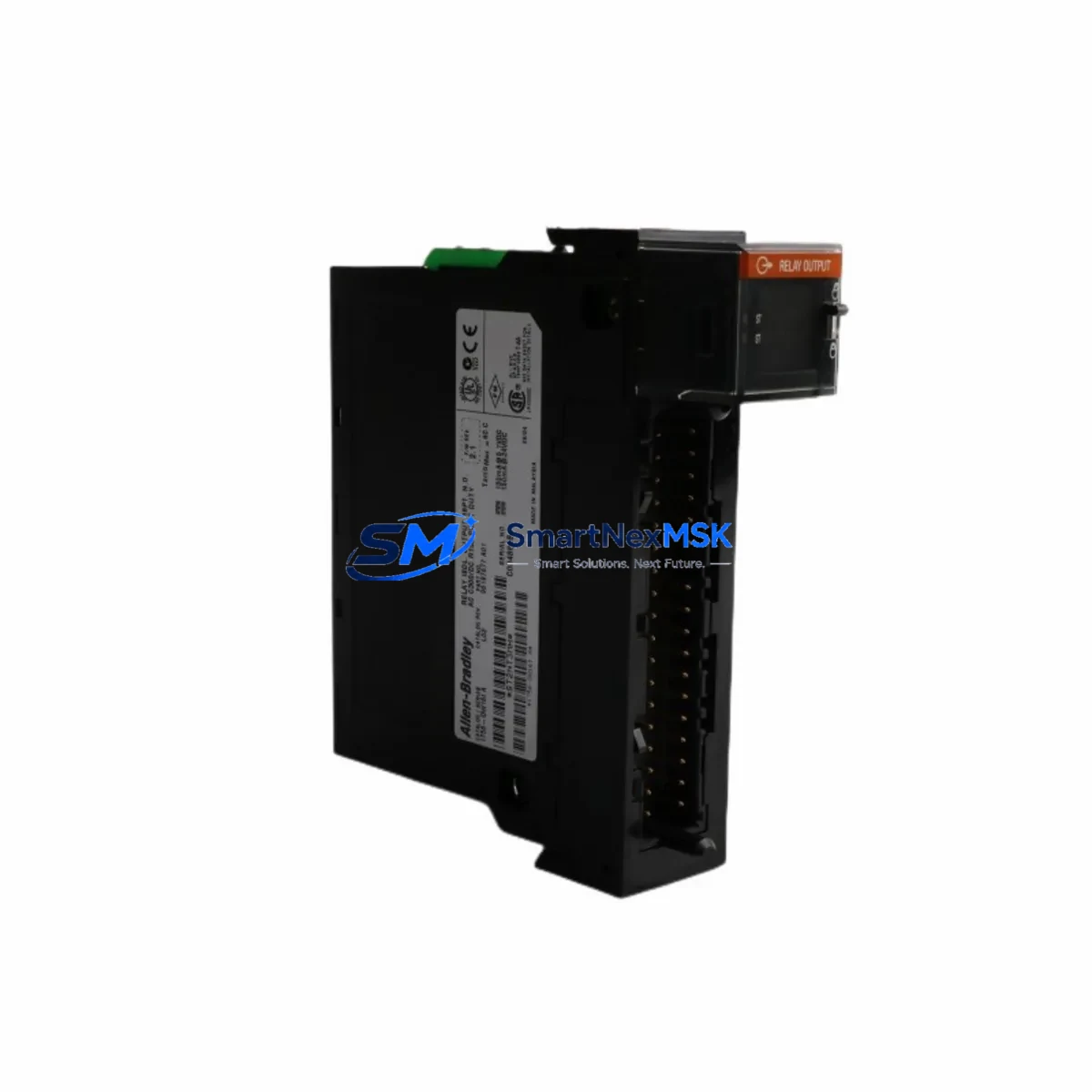
The Allen-Bradley 1756-OW16I is a 16-point isolated relay output module designed for the ControlLogix 1756 platform — one of the most widely deployed programmable automation controller (PAC) architectures in discrete manufacturing, oil & gas, water treatment, and heavy industry. As a maintenance-ready original spare, the 1756-OW16I is engineered to deliver direct drop-in replacement capability, enabling maintenance engineers to restore system operation with minimal reconfiguration and zero firmware compatibility risk.
For facilities running continuous or semi-continuous processes, an unplanned relay output module failure can cascade into full line shutdowns. Stocking a verified original 1756-OW16I spare — pre-tested, serialized, and shipped with a 12-month warranty — is the most effective single action a maintenance team can take to reduce mean time to repair (MTTR) on ControlLogix-based control panels.
This module supports isolated relay contacts rated for both AC and DC loads, making it suitable for driving motor starters, solenoid valves, pilot lights, and interlock circuits across a wide range of industrial field devices. Its slot-based backplane installation in the 1756 chassis means replacement requires no special tooling — a trained technician can complete a hot-swap or cold-swap procedure in under 15 minutes when a verified spare is on hand.
Spare Maintenance Table
| Parameter | Specification |
|---|---|
| Part Number / SKU | 1756-OW16I |
| Brand / Manufacturer | Allen-Bradley (Rockwell Automation) |
| Series | ControlLogix 1756 |
| Module Type | Isolated Relay Output Module |
| Output Points | 16 (individually isolated) |
| Output Type | Relay (Form A / SPST-NO) |
| Load Voltage Range | 5–265 V AC / 5–125 V DC |
| Max Load Current per Point | 2 A (resistive) |
| Backplane Current Draw | 120 mA @ 5 VDC |
| Chassis Compatibility | 1756 ControlLogix chassis (all slot counts) |
| Controller Compatibility | 1756-L6x, 1756-L7x, 1756-L8x series |
| Operating Temperature | 0–60 °C |
| Relative Humidity | 5–95% non-condensing |
| Mounting | Backplane slot, tool-free keying |
| Certifications | UL, CE, cUL |
| Country of Origin | United States |
| Condition | Original, new or reconditioned-to-spec |
| Pre-shipment Testing | Yes — functional output verification |
| Warranty | 12 Months from date of shipment |
| Typical Lead Time | Ships within 1–3 business days |
Maintenance Planning for Continuous Operation
When a 1756-OW16I relay output module is flagged during a control cabinet inspection or fails in service, experienced maintenance engineers know that the module itself is rarely the only component that warrants attention. A thorough site assessment during the replacement window should include the following associated components and subsystems:
Begin with the 1756 chassis and backplane — inspect for backplane connector wear, corrosion, or mechanical damage that may have contributed to the module failure. If the chassis is a legacy 1756-A7 or 1756-A13, verify that the backplane power budget is within spec after the replacement module is installed. The 1756-PA72 or 1756-PB72 power supply module should be load-tested; a degraded power supply is a common root cause of intermittent relay output faults and is frequently overlooked during reactive maintenance.
Check the 1756-L71 or 1756-L73 ControlLogix processor firmware revision and I/O tree configuration to confirm the replacement 1756-OW16I is recognized without requiring a full project download. In most cases, a module with the same catalog number will auto-configure; however, if the slot was previously configured for a different output module type, a partial download of the I/O configuration may be required.
Inspect all field wiring terminations at the 1756-TBCH or 1756-TBS6H removable terminal blocks. Relay output modules driving inductive loads — motor starters, solenoid valves, contactor coils — are subject to contact wear and arc erosion over time. Replace any terminal blocks showing discoloration, loose screws, or conductor insulation damage. Verify that surge suppressors or RC snubber circuits are installed across inductive loads; their absence accelerates relay contact degradation and can cause false triggering on adjacent channels.
For panels with mixed I/O, also review the 1756-IB16 or 1756-IA16 digital input modules in adjacent slots — relay output faults sometimes generate transient noise that affects nearby input modules. A 1756-IF8 analog input module or 1756-OF8 analog output module in the same chassis should be verified for correct operation after the relay module swap, particularly in process control applications where analog and discrete I/O interact in the same control loop.
If the panel includes a 1756-EN2T or 1756-EN3TR EtherNet/IP communication module, confirm that the I/O connection to the controller is re-established after the module replacement and that no connection timeout faults are logged in the controller diagnostics. In redundant controller configurations using a 1756-RM2 redundancy module, verify that the redundancy synchronization status returns to a healthy state before returning the system to automatic operation.
Finally, update your site’s spare parts register to reflect the consumed 1756-OW16I unit and initiate a replenishment order. Best practice for high-availability facilities is to maintain a minimum of one verified spare per chassis in service, with a secondary spare held at the regional warehouse level.
Site Replacement Workflow
Step 1 — Pre-replacement verification: Confirm the failed module’s catalog number (1756-OW16I) and slot position. Cross-reference with the Logix Designer I/O tree to identify which output points are affected and which field devices are de-energized. Notify operations of the planned outage window.
Step 2 — Safe isolation: Place the controller in Program mode or inhibit the affected I/O module from the Logix Designer software to prevent unintended field device actuation during the swap. For safety-critical outputs, verify that the associated field devices are in a safe state before proceeding.
Step 3 — Module removal: Disengage the removable terminal block (RTB) from the module face. Press the top and bottom locking tabs and slide the 1756-OW16I out of the chassis slot. Note the module keying position for reference.
Step 4 — Replacement installation: Insert the new 1756-OW16I into the same slot. The module will auto-configure from the controller’s stored I/O configuration in most cases. Reconnect the RTB and verify that all terminal screws are torqued to specification (typically 0.5–0.6 N·m for 1756-series RTBs).
Step 5 — Functional verification: Return the controller to Run mode. Force-test each output channel from Logix Designer to confirm relay contact closure and field device response. Check the controller diagnostics for any I/O fault codes. Document the replacement in the site maintenance log with the new module’s serial number and date of installation.
Step 6 — System handover: Notify operations that the system is restored. Update the spare parts inventory record and initiate a replenishment order for the consumed 1756-OW16I spare.
Spare Parts Support FAQ
Q1: Is this 1756-OW16I compatible with all ControlLogix chassis and controller revisions?
Yes. The 1756-OW16I is compatible with all standard 1756 ControlLogix chassis (4, 7, 10, 13, and 17-slot) and all 1756-series controllers including the L6x, L7x, and L8x families. No firmware upgrade is required for the module itself — it is configured entirely through the Logix Designer project. If replacing a module in a legacy system running an older controller firmware, verify that the I/O module catalog number is supported in the installed firmware revision using Rockwell’s compatibility matrix.
Q2: What pre-shipment testing is performed on this spare?
Every 1756-OW16I unit shipped by SMARTNEXMSK undergoes functional output verification prior to dispatch. Each relay channel is tested for contact closure, contact resistance, and isolation integrity. Units are shipped with a test report and are covered by a 12-month warranty from the date of shipment. If a unit fails to perform as specified upon receipt, contact our technical support team for immediate replacement or credit.
Q3: How should I manage 1756-OW16I spare inventory for a multi-chassis facility?
For facilities operating three or more ControlLogix chassis, we recommend maintaining a minimum of two 1756-OW16I spares in the site stores, with one additional unit held at the regional distribution level. Relay output modules have a finite contact life (typically rated at 100,000–500,000 operations depending on load type), so high-cycle applications — such as those driving motor starters or solenoid valves at high frequency — should be inspected at each planned shutdown and replaced proactively based on cycle count rather than waiting for failure.
Q4: Can this module replace older or discontinued Allen-Bradley relay output modules?
The 1756-OW16I is the current catalog number for the 16-point isolated relay output module in the ControlLogix 1756 platform. It is the direct replacement for earlier revisions of the same catalog number. For legacy systems using older 1756-series relay output modules with different catalog numbers (such as the 1756-OW16 non-isolated variant), verify the wiring configuration and I/O tree settings before substitution, as the isolated and non-isolated variants have different terminal block wiring schemes. SMARTNEXMSK technical support can assist with compatibility verification prior to order.
© 2026 SMARTNEXMSK. All rights reserved.
Original Source: https://smartnexmsk.com
Contact: sales@smartnexmsk.com | +86 18259474341


