Allen-Bradley 1756-OX8I Maintenance-Ready Spare for ControlLogix Automation
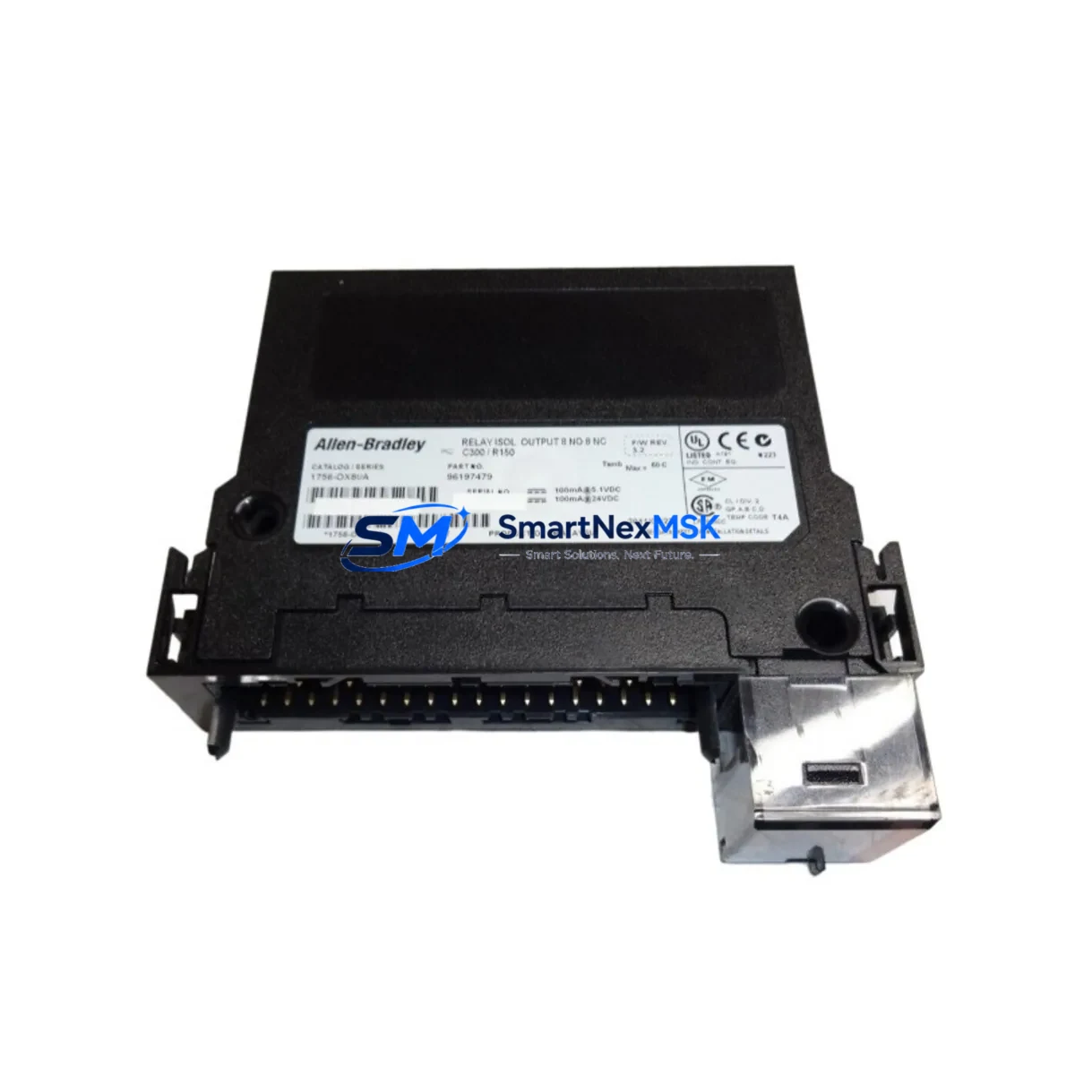
The Allen-Bradley 1756-OX8I is an 8-point isolated relay output module designed for the ControlLogix 1756 Series backplane architecture. As a critical switching interface between the PLC control system and field devices — including motor starters, solenoid valves, pilot lights, and high-voltage actuators — this module is a frontline component in industrial automation reliability. Maintaining a verified spare of the 1756-OX8I in your parts inventory is one of the most effective strategies for minimizing unplanned downtime in ControlLogix-based control systems.
Each unit supplied by SMARTNEXMSK is sourced as an original Allen-Bradley spare, inspected prior to dispatch, and backed by a 12-month warranty. Whether you are managing a planned shutdown, responding to an emergency relay failure, or building out a preventive maintenance kit for a multi-cabinet ControlLogix installation, the 1756-OX8I is a high-priority line item on any serious spare parts list.
Spare Maintenance Table
| Part Number / SKU | 1756-OX8I |
| Brand | Allen-Bradley (Rockwell Automation) |
| Series | ControlLogix 1756 |
| Module Type | Isolated Relay Output Module |
| Output Points | 8 Points (individually isolated) |
| Output Type | Relay (Form C — SPDT) |
| Voltage Range | 10–265V AC / 5–150V DC |
| Current Rating | 2A per point (resistive load) |
| Isolation | Point-to-point isolation (no common return) |
| Backplane Compatibility | ControlLogix 1756 Series chassis (all slot counts) |
| Communication | Via ControlLogix backplane (1756-ENxT, 1756-CN2, etc.) |
| Operating Temperature | 0°C to 60°C |
| Certifications | UL, CE, cUL |
| Origin | United States (Allen-Bradley / Rockwell Automation) |
| Replacement Compatibility | Direct drop-in for existing 1756-OX8I installations |
| Warranty | 12 Months — Tested and verified before shipment |
| Condition | Original spare — new or surplus stock |
| Lead Time | In-stock: ships within 1–3 business days |
Maintenance Planning for Continuous Operation
When a 1756-OX8I relay output module fails or is flagged during a routine control cabinet inspection, the replacement process should be treated as part of a broader system health review. Relay output modules operate under electrical stress — switching inductive and resistive loads repeatedly — and their failure often signals that adjacent components in the same control loop or cabinet deserve attention.
Maintenance engineers should simultaneously inspect the 1756-PA75 or 1756-PB75 power supply module feeding the chassis, as voltage irregularities are a common upstream cause of relay contact degradation. The 1756-A7 or 1756-A13 chassis backplane should be checked for slot connector wear, especially in high-vibration environments. If the 1756-OX8I is used to switch motor starters or contactors, the associated 1756-IA16 or 1756-IB16 digital input modules monitoring feedback signals should be verified for correct status reporting.
In systems where the relay outputs interface with safety circuits or emergency stop loops, the 1756-L7x or 1756-L8x ControlLogix controller firmware version should be confirmed compatible with the replacement module’s revision. Communication integrity via the 1756-EN2T EtherNet/IP communication module should be validated post-replacement to ensure I/O tree updates are correctly reflected in the controller.
For cabinets with mixed output types, it is good practice to also inspect nearby 1756-OB16 or 1756-OA16 solid-state output modules for thermal stress indicators, particularly if the relay module failure was caused by an overload event. Terminal blocks and wiring connected to the 1756-OX8I’s removable terminal assembly (RTB) — typically a 1756-TBCH or 1756-TBS6H — should be inspected for loose connections, arc marks, or insulation damage before the new module is commissioned.
Where signal isolation is required between the PLC output and field devices, consider verifying the integrity of any signal isolators or relay interposing modules in the circuit. Fuse holders and branch circuit protection upstream of the relay outputs should also be tested as part of the commissioning checklist.
Site Replacement Workflow
Step 1 — Identify and isolate: Confirm the failed slot using the ControlLogix controller’s I/O tree in Studio 5000 Logix Designer. Note the slot number, chassis ID, and current module revision before powering down the affected circuit.
Step 2 — Safe removal: De-energize the relay output circuit at the field device level. Disconnect the RTB (removable terminal block) from the module face before extracting the module from the chassis slot. Label all field wiring if not already documented.
Step 3 — Verify replacement compatibility: Confirm the replacement 1756-OX8I matches the catalog number and firmware revision required by the controller project file. SMARTNEXMSK provides module revision details upon request to support compatibility verification before shipment.
Step 4 — Install and commission: Insert the replacement module into the same chassis slot. Reconnect the RTB. Power up the circuit and verify the module status LED indicates normal operation (solid green). Confirm all 8 output points respond correctly to controller commands via forced I/O test in Studio 5000.
Step 5 — Document and restock: Update the maintenance log with the replacement date, module serial number, and any observations. Immediately initiate a reorder for the consumed spare to maintain minimum stock levels. For facilities running multiple ControlLogix chassis, a minimum of one 1756-OX8I per installation is the recommended baseline inventory posture.
Spare Parts Support FAQ
Q1: Is the 1756-OX8I supplied by SMARTNEXMSK an original Allen-Bradley part?
Yes. All units are sourced as original Allen-Bradley / Rockwell Automation components — new or verified surplus stock. Each module undergoes pre-shipment inspection and functional verification. A 12-month warranty is included with every unit.
Q2: Can the 1756-OX8I be installed in any ControlLogix 1756 chassis without reconfiguration?
Yes. The 1756-OX8I is a direct drop-in replacement for any existing 1756-OX8I installation within the ControlLogix 1756 chassis family. No hardware reconfiguration is required. The controller project file will automatically recognize the module in the same slot, provided the catalog number and revision are consistent with the existing configuration.
Q3: How quickly can SMARTNEXMSK ship the 1756-OX8I for an emergency breakdown?
In-stock units are dispatched within 1–3 business days. For urgent breakdown situations, contact our sales team directly at sales@smartnexmsk.com or +86 18259474341 to confirm real-time stock availability and expedited shipping options. We support emergency procurement for maintenance teams globally.
Q4: What is the recommended spare parts strategy for ControlLogix relay output modules?
For facilities with continuous production requirements, we recommend maintaining a minimum of one 1756-OX8I per ControlLogix chassis in active service. For multi-chassis installations or systems with high relay switching cycles, a 2:1 spare ratio per chassis is advisable. Pairing the relay output spare with a compatible RTB (1756-TBCH) and a power supply spare (1756-PA75) creates a complete emergency kit capable of restoring full chassis output capability without waiting for additional parts.
© 2026 SMARTNEXMSK. All rights reserved.
Original Source: https://smartnexmsk.com
Contact: sales@smartnexmsk.com | +86 18259474341


