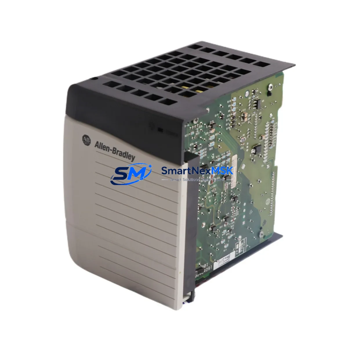
Allen-Bradley 1756-PB75 Retrofit-Ready DC Power Supply for ControlLogix Control Systems
The Allen-Bradley 1756-PB75 is a 24VDC input power supply module designed for the ControlLogix 1756 chassis platform. As legacy automation infrastructure ages and OEM support windows close, the 1756-PB75 has become one of the most sought-after retrofit components for engineers tasked with sustaining continuous production on existing ControlLogix-based control systems. This unit delivers 75W of regulated DC power to the 1756 backplane, supporting mixed I/O and communication module configurations without requiring chassis replacement or controller re-programming.
Whether you are replacing a failed unit on an active production line, building a spare-parts inventory for a multi-site facility, or executing a planned upgrade from an earlier ControlLogix power supply variant, the 1756-PB75 provides a verified drop-in solution. Each unit shipped by SMARTNEXMSK is function-tested prior to dispatch and covered by a 12-month warranty against manufacturing defects and operational failure.
Upgrade Compatibility Table
| Parameter | 1756-PB75 Specification | Retrofit Notes |
|---|---|---|
| Input Voltage | 18–32 VDC | Verify site DC bus voltage before installation; incompatible with AC-only panels without a rectifier stage |
| Output Power | 75W backplane power | Sufficient for chassis configurations up to 10 slots with standard I/O mix; calculate total module draw before commissioning |
| Chassis Compatibility | 1756-A4, 1756-A7, 1756-A10, 1756-A13, 1756-A17 | Direct backplane slot fit; no adapter required |
| Controller Compatibility | 1756-L61, 1756-L62, 1756-L63, 1756-L71, 1756-L72, 1756-L73 | No firmware change required on controller side |
| Communication Module Support | 1756-EN2T, 1756-CN2, 1756-DNB, 1756-DHRIO | Power budget must account for communication module draw; EN2T draws approx. 3.5W |
| Terminal Wiring | Screw-terminal DC input block | Reuse existing 24VDC field wiring; confirm polarity and wire gauge (AWG 14–22 recommended) |
| Replacement for | 1756-PA75, 1756-PB72 (legacy) | Physical form factor identical; confirm input voltage type (AC vs DC) when substituting 1756-PA75 |
| Commissioning | No module addressing required | Power supply is transparent to RSLogix 5000 / Studio 5000 project; no program modification needed |
| Warranty | 12 Months | Covers operational failure and manufacturing defects from date of shipment |
Retrofit Planning for Existing Automation Systems
A successful 1756-PB75 retrofit begins well before the replacement unit arrives on site. The first step is a full power budget audit of the target chassis. Engineers should document the current draw of every installed module — including the 1756-L7x series controller, any 1756-EN2T EtherNet/IP communication modules, 1756-IB16 or 1756-OB16 digital I/O modules, and any 1756-IF8 or 1756-OF8 analog I/O modules — and confirm that the aggregate load remains within the 75W backplane output rating of the 1756-PB75.
Terminal block wiring is the next critical checkpoint. The 1756-PB75 accepts 18–32VDC at its input terminals. If the existing panel was previously powered by a 1756-PA75 AC power supply, the field wiring infrastructure will need to be adapted to a DC source — typically a 24VDC SMPS (switched-mode power supply) rated for the combined chassis load plus a 20% safety margin. Confirm wire gauge, polarity labeling, and fuse sizing before energizing the replacement unit.
For systems running ControlNet via a 1756-CN2 module or DeviceNet via a 1756-DNB bridge, communication link continuity must be verified after power restoration. Network topology maps and node address tables should be documented before shutdown to accelerate re-commissioning. Similarly, if the control system interfaces with a PanelView Plus HMI terminal over EtherNet/IP, confirm that the HMI application’s tag database references remain intact after the power cycle — particularly for systems where the 1756-L6x controller holds the IP address assignment in non-volatile memory.
Backplane slot position of the power supply is fixed at slot 0 of the 1756 chassis. No module address configuration is required in the RSLogix 5000 or Studio 5000 project file. The replacement 1756-PB75 is recognized automatically upon chassis power-up. If the system uses a 1756-RM redundancy module pair, both chassis power supplies should be replaced in the same maintenance window to maintain redundancy integrity.
For facilities maintaining a critical spare inventory, it is advisable to stock at least one 1756-PB75 per active ControlLogix chassis, alongside a matched 1756-L7x controller backup and a spare 1756-EN2T communication module. This three-component spare set covers the majority of unplanned outage scenarios without requiring emergency procurement.
Downtime Control During System Migration
Minimizing production downtime during a 1756-PB75 replacement requires a structured pre-shutdown sequence. Before de-energizing the chassis, use Studio 5000 or RSLogix 5000 to perform a full project upload from the controller and save the .ACD file to a secure backup location. If the controller is a 1756-L71 or later with SD card support, verify that the project image on the SD card is current — this provides an additional recovery path if the controller memory is cleared during the power interruption.
For processes where even brief interruptions are critical, consider placing the controller in Remote Program mode and using the I/O force table to hold critical output states before cutting chassis power. Document all forced values and clear forces immediately after the replacement unit is confirmed operational, to prevent latent logic conflicts during normal run mode.
Physical swap time for the 1756-PB75 is typically under five minutes: remove the DC input wiring, release the module locking tab, slide the old unit out of slot 0, insert the replacement, reconnect and torque the terminal screws to specification, and restore DC power. The ControlLogix chassis performs an automatic backplane self-test on power-up; the controller will return to Run mode within seconds if the project is intact and all I/O modules respond normally.
Post-replacement verification should include confirming all I/O module status LEDs return to steady green, checking the controller diagnostic log in Studio 5000 for any fault codes, and verifying communication link status on all installed 1756-EN2T or 1756-CN2 modules. For systems with SCADA integration, confirm that the historian and alarm server re-establish their OPC or EtherNet/IP connections without manual intervention.
Retrofit Support FAQ
Q: Is the 1756-PB75 a direct replacement for the 1756-PA75?
A: The 1756-PB75 and 1756-PA75 share the same physical form factor and backplane connector, but they differ in input voltage type. The 1756-PA75 accepts 85–265VAC, while the 1756-PB75 requires 18–32VDC. Before substituting one for the other, confirm that your panel’s power distribution infrastructure matches the input requirement of the replacement unit. No changes to the controller program or chassis configuration are needed regardless of which variant is installed.
Q: Will replacing the power supply affect my RSLogix 5000 / Studio 5000 program?
A: No. The 1756-PB75 is transparent to the controller project. The power supply does not appear as a configurable object in the I/O tree, and its replacement does not alter controller memory, tag values, or program logic. After power restoration, the controller resumes execution from the point defined by its configured power-loss behavior (typically Resume or Restart, as set in the controller properties).
Q: What pre-shipment testing does SMARTNEXMSK perform on the 1756-PB75?
A: Every 1756-PB75 unit undergoes functional load testing at rated output power prior to dispatch. Output voltage regulation, input protection response, and backplane connector integrity are verified. Units that do not meet OEM specification tolerances are quarantined and not shipped. A test report is available upon request. All shipped units are covered by a 12-month warranty from the date of shipment.
Q: How do I verify compatibility with my specific ControlLogix chassis and firmware revision?
A: The 1756-PB75 is compatible with all 1756-series chassis variants (1756-A4 through 1756-A17) and is firmware-agnostic — it operates independently of the controller firmware version. For mixed-revision environments or systems running older 1756-L6x controllers alongside newer 1756-L8x controllers in a redundant configuration, contact our technical team at sales@smartnexmsk.com with your chassis catalog number and controller firmware revision for a pre-sale compatibility confirmation.
© 2026 SMARTNEXMSK. All rights reserved.
Original Source: https://smartnexmsk.com
Contact: sales@smartnexmsk.com | +86 18259474341


