Allen-Bradley 1756-RIO Retrofit-Ready Remote I/O Scanner for ControlLogix Systems
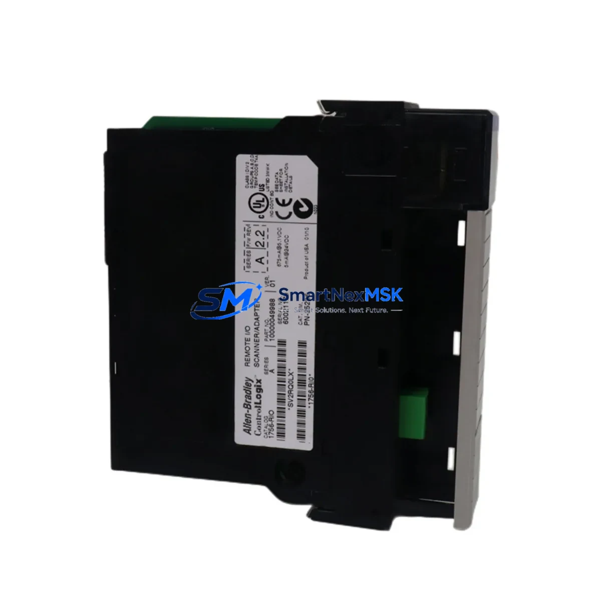
The Allen-Bradley 1756-RIO Remote I/O Scanner Module is a critical communication bridge within the ControlLogix platform, enabling legacy Remote I/O (RIO) networks to remain operational within modern 1756-series chassis environments. As aging PLC-5 and SLC 500 installations reach end-of-life, the 1756-RIO provides a validated, drop-in retrofit path that preserves existing field wiring, I/O addressing, and ladder logic structures — dramatically reducing the engineering effort and downtime risk associated with full system replacement.
At SMARTNEXMSK, we maintain verified stock of the 1756-RIO with full functional testing, 12-month warranty coverage, and rapid global dispatch. Every unit is inspected against Allen-Bradley factory specifications before shipment, ensuring compatibility with your existing 1756 backplane, power supply, and controller configuration.
Upgrade Compatibility Table
| Parameter | Details |
|---|---|
| Module SKU | 1756-RIO |
| Series / Platform | ControlLogix 1756 Series |
| Primary Function | Remote I/O Scanner – bridges legacy RIO network to ControlLogix backplane |
| Backplane Interface | 1756 ControlLogix backplane (any 1756-Ax chassis slot) |
| Communication Protocol | Allen-Bradley Remote I/O (RIO) – 57.6K / 115.2K / 230.4K baud |
| Replaces / Upgrades From | PLC-5 RIO scanner cards, SLC 500 1747-SN, legacy 1771-ASB adapter systems |
| Installation Requirement | 1756 chassis slot; 1756-PA72 or 1756-PB72 power supply recommended |
| Address Configuration | Module address set via RSLogix 5000 / Studio 5000 I/O tree; rack/group/slot mapping required |
| Program Compatibility | Existing RIO ladder logic transferable; verify rack size and I/O image table mapping |
| HMI Compatibility | Compatible with PanelView Plus via ControlLogix tag-based addressing after migration |
| Commissioning Tool | Studio 5000 Logix Designer v21 and above |
| Warranty | 12-Month Warranty – SMARTNEXMSK functional test certified |
Retrofit Planning for Existing Automation Systems
Successful integration of the 1756-RIO into a brownfield control system requires a structured pre-migration assessment. Engineers should begin by auditing the existing RIO network topology — documenting all adapter nodes, rack addresses, and I/O module types currently served by the legacy scanner. In PLC-5 environments, the 1771-ASB remote adapter and associated 1771-series I/O modules (such as 1771-OAD output modules and 1771-IAD input modules) will remain in place on the remote racks; the 1756-RIO replaces only the scanner function at the ControlLogix end.
Power budget verification is essential before installation. The 1756-RIO draws from the 1756 backplane, so confirm that the installed 1756-PA72 or 1756-PB72 power supply has sufficient remaining capacity after accounting for all other modules in the chassis — including the 1756-L73 or 1756-L85E controller, any 1756-EN2T EtherNet/IP communication modules, and installed 1756-IB16 or 1756-OB16E I/O modules. Overloading the backplane power supply is a common commissioning error that causes intermittent faults.
Terminal wiring at the RIO cable connection points must be verified against the original network drawing. The 1756-RIO uses a standard blue-hose RIO cable (Belden 9463 or equivalent) with the same daisy-chain topology as the legacy system. Confirm cable shield grounding at one end only to prevent ground loops. If the existing cable run exceeds recommended lengths for the selected baud rate, a 1756-RIO baud rate reduction may be necessary — this must be reflected in the Studio 5000 module configuration.
For sites running mixed communication architectures — for example, where a 1756-DNB DeviceNet Bridge or a 1756-MVI46 Modbus interface module is also present in the chassis — the 1756-RIO slot assignment must be planned to avoid address conflicts in the I/O tree. The 1756-ENBT or 1756-EN2T modules handling upstream EtherNet/IP traffic to the SCADA or DCS layer should be configured and tested independently before the RIO migration begins, ensuring that network-layer communications remain stable throughout the cutover window.
Where HMI screens built on PanelView Plus terminals reference PLC-5 data file addresses (N7, F8, B3, etc.), a tag remapping exercise in FactoryTalk View Studio will be required post-migration. Plan this work in parallel with the I/O tree rebuild in Studio 5000 to compress the overall project timeline.
Downtime Control During System Migration
Minimizing production downtime during a 1756-RIO retrofit requires a phased cutover strategy. The recommended approach is to pre-configure the replacement ControlLogix chassis — including the 1756-L73 controller, 1756-RIO scanner, and all required communication modules — offline using Studio 5000, with the full I/O tree, rack definitions, and tag database built and verified before the maintenance window opens.
During the cutover window, the sequence should follow: (1) place the existing PLC-5 or SLC 500 system in a safe hold state with all outputs de-energized; (2) disconnect the RIO cable from the legacy scanner and connect to the 1756-RIO; (3) power up the new ControlLogix chassis and verify backplane communication; (4) download the pre-tested program to the 1756-L73 or equivalent controller; (5) go online and verify all RIO rack adapters are recognized in the I/O tree; (6) perform a controlled output test on each rack before returning to automatic mode.
Retaining the original PLC-5 or SLC 500 system in a powered-but-isolated state during the first production run provides a rapid fallback path if unexpected field issues arise. Original program files should be archived to both local engineering workstation and off-site backup before any hardware changes begin. This approach has consistently allowed our customers to complete 1756-RIO retrofit cutovers within a single 8-hour maintenance shift, protecting production schedules and reducing the financial impact of unplanned downtime.
Retrofit Support FAQ
Q: Can the 1756-RIO directly replace a PLC-5 RIO scanner without rewiring the remote racks?
A: Yes. The 1756-RIO connects to the existing RIO cable network using the same Belden 9463 blue-hose cable. Remote racks with 1771-ASB adapters and 1771-series I/O modules remain unchanged. Only the scanner end — previously a PLC-5 integrated scanner or a dedicated scanner card — is replaced by the 1756-RIO in the new ControlLogix chassis.
Q: What commissioning steps are required after installing the 1756-RIO?
A: After physical installation, open Studio 5000 Logix Designer and add the 1756-RIO to the I/O tree. Configure the baud rate to match the existing RIO network (typically 57.6K or 115.2K baud). Define each remote rack by rack number, starting group, and rack size. Download the configuration, go online, and verify that all adapter nodes appear with a green status. Perform a forced I/O test on each rack before enabling automatic control.
Q: Is the 1756-RIO compatible with both 1756-L6x and 1756-L8x series controllers?
A: Yes. The 1756-RIO is compatible with all current ControlLogix controllers including the 1756-L61, 1756-L62, 1756-L63, 1756-L71, 1756-L73, 1756-L83E, and 1756-L85E, provided the chassis and power supply are correctly sized. Firmware version requirements should be verified in the Studio 5000 compatibility matrix for your specific controller revision.
Q: What warranty and pre-shipment testing does SMARTNEXMSK provide for the 1756-RIO?
A: Every 1756-RIO unit shipped by SMARTNEXMSK undergoes functional verification testing prior to dispatch, including backplane communication check and RIO port integrity test. All units are covered by a 12-month warranty from the date of shipment. In the event of a confirmed hardware fault within the warranty period, SMARTNEXMSK will arrange priority replacement to minimize impact on your production operations. Contact sales@smartnexmsk.com for warranty claims and technical support.
© 2026 SMARTNEXMSK. All rights reserved.
Original Source: https://smartnexmsk.com
Contact: sales@smartnexmsk.com | +86 18259474341


