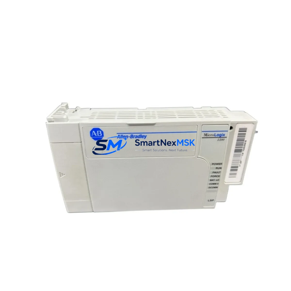
Allen-Bradley 1764-LSP Maintenance-Ready Spare for MicroLogix 1500 Automation
The Allen-Bradley 1764-LSP is the standard processor unit for the MicroLogix 1500 programmable controller platform — a compact, high-performance PLC widely deployed in discrete manufacturing, material handling, packaging lines, and building automation systems. As a maintenance-ready original spare, the 1764-LSP is sourced, inspected, and dispatched to support rapid field replacement, minimizing unplanned downtime and protecting production continuity.
For maintenance engineers managing aging MicroLogix 1500 installations, holding a verified 1764-LSP in the spare parts cabinet is a fundamental risk-reduction measure. The processor integrates directly with the 1764-24BWA or 1764-28BXB base units and supports the full MicroLogix 1500 I/O expansion architecture. Its onboard memory, communication ports, and ladder logic execution engine are factory-configured to Allen-Bradley specifications, ensuring drop-in compatibility without re-engineering the control program.
Procurement engineers sourcing replacement processors for multi-site facilities will find that the 1764-LSP remains one of the most widely stocked MicroLogix components in the industrial aftermarket. Each unit shipped from SMARTNEXMSK undergoes pre-dispatch functional verification and is covered by a 12-month warranty, providing documented assurance for maintenance records and audit compliance.
Spare Maintenance Table
| Parameter | Specification |
|---|---|
| SKU / Part Number | 1764-LSP |
| Brand | Allen-Bradley (Rockwell Automation) |
| Series | MicroLogix 1500 |
| Product Type | PLC Processor Module |
| Compatible Base Units | 1764-24BWA, 1764-28BXB |
| Communication Ports | RS-232 (DH-485 / DF1), isolated serial |
| Program Memory | Up to 6K instructions (user program) |
| Data Memory | Up to 6K words |
| I/O Expansion | Supports 1769 Compact I/O expansion modules |
| Operating Voltage | Supplied via base unit (24 VDC or 120/240 VAC depending on base) |
| Operating Temperature | 0 °C to 60 °C (32 °F to 140 °F) |
| Relative Humidity | 5% to 95% non-condensing |
| Mounting | DIN rail or panel mount via base unit |
| Origin | USA (Allen-Bradley / Rockwell Automation) |
| Condition | Original spare — new or tested-good surplus |
| Pre-Dispatch Testing | Functional verification before shipment |
| Warranty | 12 months from date of delivery |
| Certifications | UL Listed, CE Marked, cUL |
| Maintenance Recommendation | Replace processor if fault LED is persistent, program corruption detected, or communication failure is isolated to processor |
Maintenance Planning for Continuous Operation
When a MicroLogix 1500 system requires processor replacement, experienced maintenance engineers know that the 1764-LSP rarely fails in isolation. A thorough site replacement protocol should include inspection and functional verification of the surrounding control architecture to prevent repeat faults and ensure the restored system operates reliably.
Begin with the 1764-24BWA or 1764-28BXB base unit — the processor seats directly into the base, and worn or corroded backplane connectors can cause intermittent processor faults that mimic processor failure. Inspect the base unit’s terminal blocks and I/O wiring for signs of overheating or insulation degradation.
Check the 24 VDC power supply feeding the base unit. Voltage sag or ripple outside Allen-Bradley’s specified tolerance will cause processor resets and memory errors. A replacement 1606-XLP power supply or equivalent DIN-rail 24 VDC unit should be on hand for any MicroLogix 1500 panel.
Inspect all 1769 Compact I/O expansion modules connected to the system — including digital input modules (1769-IQ16), digital output modules (1769-OB16), and analog I/O modules (1769-IF4). A failed I/O module can generate processor fault codes that are misdiagnosed as processor failure. Verify each module’s status LED and check for blown fuses on output modules.
Review the RS-232 communication cable and any 1761-NET-AIC Advanced Interface Converter used for DH-485 network connectivity. Communication faults at the network level can prevent program upload/download and are often confused with processor hardware failure. If the system uses 1747-PIC or 1784-U2DHP USB-to-DH+ adapters for programming, verify driver compatibility with the replacement processor firmware.
For panels with PanelView 300 or PanelView 550 HMI terminals communicating via DH-485, confirm that the HMI communication parameters match the replacement processor’s node address and baud rate settings. HMI communication loss after processor swap is a common post-replacement issue that delays restart.
Inspect relay output modules and interposing relays in the output circuit. High-cycle relay contacts degrade over time and can cause output faults that stress the processor’s diagnostic routines. Replace any relay showing contact resistance above specification.
Finally, verify the integrity of signal isolation barriers and surge protection devices on analog input channels. Transient overvoltage events that damage analog signal conditioning components are a leading cause of processor and I/O module failure in industrial environments. Installing or replacing Phoenix Contact or Weidmüller signal isolators on critical analog loops is a recommended preventive measure during any planned processor replacement.
Site Replacement Workflow
Step 1 — Backup the existing program. Before removing the 1764-LSP, use RSLogix 500 or Studio 5000 Logix Designer to upload and save the current ladder logic program, including all data files, PID configurations, and communication settings. Store the backup on a secure engineering workstation and document the processor firmware revision.
Step 2 — De-energize and isolate. Follow your site’s lockout/tagout (LOTO) procedure. Disconnect the base unit from the power supply and verify zero energy state before removing the processor module.
Step 3 — Remove and inspect. Slide the 1764-LSP out of the base unit. Inspect the backplane connector on both the processor and the base for bent pins, corrosion, or debris. Clean with dry compressed air if necessary.
Step 4 — Install the replacement 1764-LSP. Seat the new processor firmly into the base unit until the locking tab engages. Re-energize the system and verify that the processor powers up without fault LEDs.
Step 5 — Download the program. Using RSLogix 500, download the saved program to the replacement processor. Verify all data files, retentive data, and communication node addresses are correctly restored.
Step 6 — Functional test. Run the system through a controlled startup sequence. Verify all I/O points, HMI communication, and network connectivity before returning the system to production. Document the replacement in the maintenance log with the new processor serial number and warranty start date.
This workflow supports a target replacement time of under two hours for a prepared maintenance team, significantly reducing mean time to repair (MTTR) for MicroLogix 1500 systems.
Spare Parts Support FAQ
Q1: Is the 1764-LSP still available as a new original spare, or only as surplus?
The 1764-LSP has reached end-of-life status in Rockwell Automation’s active product catalog, but original new and tested-good surplus units remain available through authorized industrial spare parts suppliers. SMARTNEXMSK maintains stock of verified 1764-LSP processors and performs pre-dispatch functional testing on all units. Each unit is shipped with a 12-month warranty covering defects in materials and workmanship.
Q2: How do I confirm compatibility between the 1764-LSP and my existing MicroLogix 1500 base unit?
The 1764-LSP is compatible with both the 1764-24BWA (24-point, 120/240 VAC power) and 1764-28BXB (28-point, 24 VDC power) base units. Compatibility is confirmed by matching the base unit catalog number on the existing hardware label. If your system uses 1769 Compact I/O expansion, the replacement processor will support the same expansion configuration without hardware changes. Contact our technical team with your base unit catalog number for confirmation before ordering.
Q3: What is included in the pre-shipment testing process?
Every 1764-LSP unit undergoes a structured pre-dispatch inspection that includes visual inspection of the backplane connector and housing, power-on functional test, communication port verification, and program memory check. Units that do not pass all test criteria are not shipped. A test record is available upon request for quality documentation purposes.
Q4: What is your recommended spare parts inventory strategy for MicroLogix 1500 systems?
For facilities operating multiple MicroLogix 1500 controllers, we recommend maintaining at least one 1764-LSP processor per five installed units as a minimum buffer stock. Given the end-of-life status of the platform, procurement engineers should consider a longer-term strategic stock of processors, base units, and key I/O modules to support system life extension beyond the standard support window. SMARTNEXMSK offers volume pricing and long-term supply agreements for facilities managing large MicroLogix 1500 installed bases.
© 2026 SMARTNEXMSK. All rights reserved.
Original Source: https://smartnexmsk.com
Contact: sales@smartnexmsk.com | +86 18259474341


