Allen-Bradley 1769-OW16 Retrofit-Ready Relay Output Module for CompactLogix Control Systems
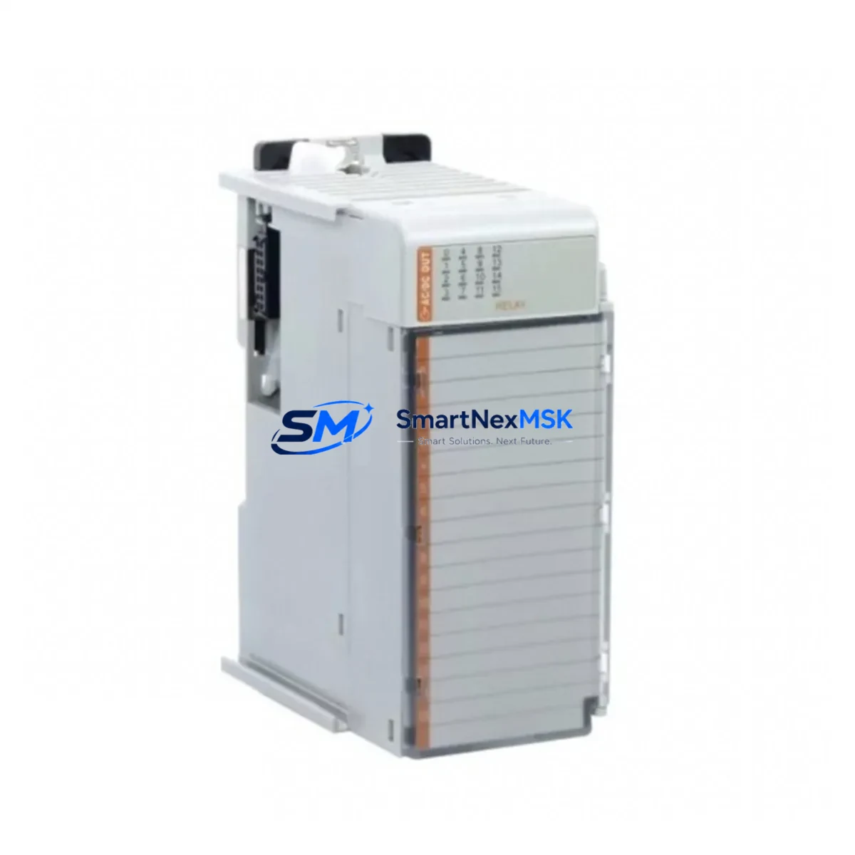
The Allen-Bradley 1769-OW16 is a 16-point relay output module designed for the CompactLogix 1769 Series control platform. As legacy automation systems reach end-of-life or require capacity expansion, the 1769-OW16 serves as a direct retrofit solution — preserving existing wiring infrastructure, backplane addressing, and ladder logic programs while delivering reliable isolated relay switching for AC and DC load circuits. Whether you are replacing a failed module in a running production line, upgrading a discontinued output card, or expanding I/O capacity in an aging control cabinet, the 1769-OW16 provides a wiring-compatible, drop-in upgrade path with minimal engineering rework.
Each relay output point on the 1769-OW16 supports both AC and DC loads, making it suitable for motor starters, solenoid valves, pilot lights, and relay coils commonly found in legacy panel designs. The module installs directly onto the 1769 backplane, occupying a single slot and drawing power from the local bus. When replacing an older 1769-series output module, engineers should verify the power supply capacity of the existing 1769-PA2 or 1769-PB2 power supply unit, as additional relay modules may increase the total bus current draw. Confirming available milliamp headroom before installation prevents nuisance faults during commissioning.
Upgrade Compatibility Table
| Parameter | Detail |
|---|---|
| Module SKU | 1769-OW16 |
| Series / Platform | Allen-Bradley CompactLogix 1769 Series |
| Output Type | Relay (isolated), 16 points |
| Load Voltage Range | 5–265V AC / 5–125V DC per point |
| Backplane Interface | 1769 side-mount bus connector (left/right expandable) |
| Installation Slot | Single-slot, any position on 1769 local or expansion bank |
| Compatible Controllers | 1769-L16ER, 1769-L18ER, 1769-L24ER, 1769-L27ERM, 1769-L30ER, 1769-L33ER, 1769-L36ERM |
| Communication Compatibility | EtherNet/IP via CompactLogix controller; no module-level protocol change required |
| Replacement Fit | Direct drop-in for 1769-OW16 and compatible with 1769-OA16 migration with wiring adaptation |
| Commissioning Requirement | Module address auto-assigned by controller; verify slot number in Studio 5000 I/O tree |
| Program Compatibility | Existing ladder logic output tags remain valid; no rung edits required for same-slot replacement |
| Warranty | 12 Months — covers manufacturing defects, functional failure, and DOA units |
Retrofit Planning for Existing Automation Systems
Successful integration of the 1769-OW16 into an existing control system begins with a thorough audit of the current panel layout. In most CompactLogix installations, the controller — typically a 1769-L30ER or 1769-L33ER — sits at the left end of the local bank, followed by a mix of analog and digital I/O modules. Before removing the failed or obsolete output module, document the terminal block wiring using the existing panel drawings or photograph each terminal row. The 1769-OW16 uses a removable terminal block, which allows the wiring harness to be transferred directly to the replacement module without re-terminating individual conductors — a significant time saver during emergency replacements.
If the retrofit involves migrating from an older SLC 500 or MicroLogix platform to CompactLogix, the 1769-OW16 is frequently specified alongside a 1769-L18ER controller and a 1769-ECR right-end cap to close the local bank. In these migration projects, the original relay output wiring from the SLC 5/04 or 1747-OW16 module can often be reused with minor terminal adapter modifications, reducing field labor costs. Engineers should also account for the 1769-IQ16 or 1769-IQ32 digital input modules that typically accompany the output bank, as the I/O map must be rebuilt in Studio 5000 Logix Designer to reflect the new slot assignments.
For systems that include analog I/O — such as the 1769-IF4 analog input module or the 1769-OF2 analog output module — the retrofit plan should confirm that the new I/O configuration does not exceed the maximum number of modules supported by the selected CompactLogix controller. The 1769-OW16 consumes backplane current from the local power supply; when combined with analog modules and communication adapters such as the 1769-L19ER or a 1769-AENTR EtherNet/IP adapter for remote expansion, the total bus load must be calculated against the rated output of the 1769-PA2 or 1769-PB4 power supply. Exceeding the rated bus current will cause the power supply to fault and prevent the system from entering run mode.
In control cabinets where space is constrained, the 1769-OW16 can be installed in a remote expansion bank connected via a 1769-AENTR adapter, extending the I/O reach without requiring a larger enclosure. This approach is common in distributed machine architectures where the main controller is located in a central panel and field I/O is distributed across multiple junction boxes. The EtherNet/IP network connecting the controller to the remote adapter must be verified for latency and packet loss before commissioning, particularly in environments with high electromagnetic interference from variable frequency drives or large motor starters.
Downtime Control During System Migration
Minimizing unplanned downtime is the primary concern during any relay output module replacement or system migration. For a like-for-like 1769-OW16 swap on a running CompactLogix system, the recommended procedure is to place the controller in Program mode, remove the faulted module, insert the replacement, and allow the controller to automatically detect and configure the new module before returning to Run mode. The entire process typically takes under 15 minutes when the replacement module is on-site and the terminal block wiring is intact.
For more complex migrations — such as transitioning from a legacy PLC-5 or SLC 500 platform — a parallel run strategy is advisable. The new CompactLogix system, including the 1769-OW16 output bank, is wired and programmed offline while the legacy system continues to control the process. Once the new program has been verified in Studio 5000 and the I/O wiring has been checked point-by-point against the original panel drawings, the cutover can be executed during a scheduled maintenance window. This approach protects the original ladder logic from accidental modification and ensures that HMI screens — whether running on a PanelView Plus 7 or a SCADA system connected via EtherNet/IP — continue to display accurate process data throughout the transition.
To further reduce risk, it is recommended to export the existing controller program as an ACD file and store a backup before making any hardware changes. If the system uses a 1769-SDN DeviceNet scanner or a 1769-SM2 serial module for legacy device communication, these modules should be tested independently before the full system cutover to confirm that field devices — including drives, sensors, and remote I/O adapters — respond correctly to the new controller’s commands. Shipping lead times for replacement modules are confirmed at order; in-stock units are dispatched within 24 hours to support emergency maintenance scenarios.
Retrofit Support FAQ
Q1: Is the 1769-OW16 a direct replacement for my existing relay output module?
Yes. The 1769-OW16 is a direct slot-for-slot replacement for any existing 1769-OW16 installed in a CompactLogix 1769 local or expansion bank. The removable terminal block allows the existing field wiring to be transferred without re-termination. If you are migrating from a different output module type — such as the 1769-OA16 AC output module — terminal wiring adaptation will be required, but the backplane slot assignment and Studio 5000 I/O tag structure remain compatible.
Q2: Will my existing ladder logic program work without modification?
For same-slot replacements, the existing program requires no modification. The controller automatically maps the new module to the same slot address, and all output tags referencing that slot remain valid. For migrations from legacy platforms such as SLC 500 or PLC-5, the program must be converted using the Logix Designer import tools or manually re-entered, as the instruction sets and addressing formats differ between platforms.
Q3: What pre-shipment testing is performed on each unit?
Every 1769-OW16 unit undergoes functional output testing prior to shipment, verifying relay coil actuation, contact continuity, and backplane communication integrity. Units are inspected for physical damage, connector condition, and firmware revision before packaging. A 12-month warranty covers all manufacturing defects and functional failures from the date of shipment. DOA units are replaced or refunded promptly upon confirmation.
Q4: How do I verify wiring compatibility before installation?
Refer to the 1769-OW16 installation instructions (publication 1769-IN059) for terminal block pinout and wiring diagrams. Compare the terminal assignments against your existing panel drawings. Pay particular attention to the common (COM) terminal groupings, as relay output modules group multiple points to shared commons — incorrect common wiring can result in load circuit faults or relay damage. If you require technical support during installation, contact our engineering team before powering the system.
© 2026 SMARTNEXMSK. All rights reserved.
Original Source: https://smartnexmsk.com
Contact: sales@smartnexmsk.com | +86 18259474341


