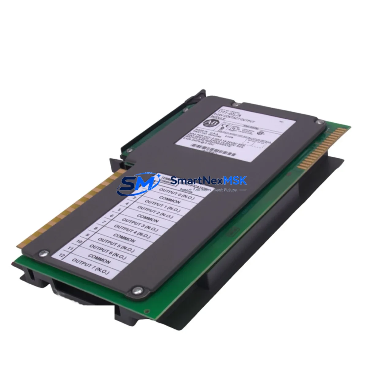
Allen-Bradley 1771-OZL Retrofit-Ready Output Module for PLC-5 Control Systems
The Allen-Bradley 1771-OZL is a 16-point, 24VDC sourcing discrete output module designed for the PLC-5 programmable controller platform. As legacy PLC-5 systems approach end-of-life and spare parts become increasingly scarce, the 1771-OZL remains one of the most sought-after replacement and upgrade components for engineers managing aging control infrastructure. Whether you are executing a like-for-like swap on a failed output card, modernizing a control cabinet, or migrating an entire production line to a newer platform, the 1771-OZL serves as a critical bridge between legacy field wiring and current automation requirements.
SMARTNEXMSK maintains verified stock of the 1771-OZL, sourced from controlled supply chains and subjected to functional testing prior to shipment. Each unit is backed by a 12-month warranty covering manufacturing defects and operational failures under normal industrial conditions.
Upgrade Compatibility Table
| Parameter | 1771-OZL Specification | Retrofit Notes |
|---|---|---|
| Output Points | 16-point discrete output | Direct replacement for 1771-OB, 1771-OBD in same slot |
| Output Voltage | 24VDC sourcing | Verify field device compatibility; sinking loads require wiring adaptation |
| Backplane Interface | 1771 I/O chassis (single-slot) | Compatible with 1771-A1B, 1771-A2B, 1771-A3B, 1771-A4B chassis |
| Module Addressing | 1-slot addressing | Confirm processor addressing mode; 2-slot addressed systems require reconfiguration |
| Communication | PLC-5 backplane protocol | Not directly compatible with ControlLogix; use 1756-DHRIO or 1771-SDN for bridge migration |
| Program Compatibility | RSLogix 5 ladder logic | Output rung references (O:xx/yy) remain valid; verify force tables and I/O maps |
| HMI Integration | PanelView 550/900/1000 via DH+ | Tag addresses unchanged if slot position is preserved |
| Installation | Single-slot, keyed module | Match keying band position to chassis slot configuration |
| Warranty | 12-Month Warranty | Covers functional failure under normal operating conditions |
Retrofit Planning for Existing Automation Systems
Successful integration of the 1771-OZL into an existing PLC-5 control system requires a structured pre-installation review. Begin by auditing the 1771 I/O chassis — common configurations include the 1771-A2B (4-slot) and 1771-A4B (16-slot) — to confirm available slot positions and current keying band assignments. The 1771-OZL occupies a single slot and must be keyed to match the chassis slot configuration to prevent incorrect module insertion.
Power budget verification is essential before adding or replacing output modules. The 1771-P4 or 1771-P7 power supply units feeding the chassis must have sufficient current capacity to support the 1771-OZL’s 24VDC output load, particularly when multiple output modules are installed in the same rack. Overloading the backplane power supply is a common cause of intermittent faults during retrofit projects.
Terminal wiring on the 1771-OZL uses a standard 40-pin wiring arm (1771-WN or equivalent). When replacing a failed module, retain the existing wiring arm if undamaged — this eliminates the need to re-terminate field cables and significantly reduces commissioning time. If the wiring arm requires replacement, document all terminal assignments before disconnection.
For systems where the PLC-5 processor communicates over a Data Highway Plus (DH+) network, the 1771-KF2 or 1771-KF3 communication interface modules must remain operational throughout the swap. Disrupting the DH+ link during a live retrofit can cause other nodes — including remote I/O adapters such as the 1771-ASB and FLEX I/O adapter modules — to fault. Plan the output module replacement during a scheduled maintenance window to avoid cascading faults across the network.
Where the retrofit scope extends beyond a single module replacement to a broader platform migration — for example, transitioning from PLC-5 to ControlLogix — the 1756-L7x or 1756-L8x controllers require a complete I/O remapping exercise. The 1771-OZL’s output data table addresses (O:xx) must be translated to ControlLogix tag-based addressing, and the RSLogix 5 program must be converted using the RSLogix 5000 import utility or manually re-entered. During the transition period, a 1756-DHRIO module can maintain DH+ connectivity to legacy devices while the new platform is commissioned in parallel.
HMI screens built on PanelView 550 or PanelView 900 terminals referencing output coil addresses tied to the 1771-OZL will continue to function without modification as long as the module occupies the same chassis slot. If the slot position changes, update the PanelView application using PanelBuilder32 before going live. For sites migrating to FactoryTalk View, a full screen rebuild is required, but the underlying control logic references can be preserved if tag naming conventions are maintained consistently.
Downtime Control During System Migration
Minimizing unplanned downtime during a 1771-OZL replacement or broader PLC-5 retrofit requires preparation at three levels: program backup, hardware staging, and field verification.
Before any physical work begins, upload and archive the current PLC-5 program using RSLogix 5. Save the program file with a timestamped filename and store it on an isolated engineering workstation — not on the plant network — to prevent accidental overwrite. Document the current I/O force table status; any forced outputs must be cleared or re-applied after the module swap to avoid unintended actuator movement during power-up.
Stage the replacement 1771-OZL alongside the existing module before the maintenance window opens. Confirm that the module’s catalog number, series letter, and firmware revision are compatible with the installed PLC-5 processor — the 5/15, 5/25, 5/40, and 5/80 processors each have specific I/O module compatibility matrices that must be verified in advance.
During the swap, de-energize the chassis slot using the processor’s I/O inhibit function rather than removing power from the entire rack. This preserves the processor’s scan cycle and keeps other I/O modules — including analog input modules such as the 1771-IFE and high-speed counter modules — online and scanning. Re-enable the slot after the new module is seated and the wiring arm is secured.
After power-up, verify output status using the RSLogix 5 data monitor before releasing the system to production. Check each of the 16 output points against the field device state to confirm correct wiring continuity. Log the commissioning results and retain them as part of the site’s maintenance record. With proper preparation, a single-module swap can be completed within a 30-minute maintenance window, and a full chassis replacement within a four-hour planned outage.
Retrofit Support FAQ
Q: Is the 1771-OZL a direct drop-in replacement for the 1771-OB or 1771-OBD?
A: The 1771-OZL is functionally equivalent to the 1771-OB series in most PLC-5 applications, but the output type differs — the OZL is a sourcing (PNP) output, while some OB variants are sinking (NPN). Verify your field device wiring polarity before substituting. No program changes are required if the slot address is preserved.
Q: What commissioning steps are required after installing a replacement 1771-OZL?
A: After seating the module and securing the wiring arm, use RSLogix 5 to go online with the processor and verify the module’s I/O status bits. Clear any I/O faults on the affected slot, confirm output data table values match expected states, and perform a point-by-point field check against the control narrative or loop diagram before returning the system to automatic mode.
Q: Can the 1771-OZL be used in a ControlLogix or CompactLogix chassis?
A: No. The 1771-OZL is designed exclusively for the 1771 I/O backplane used with PLC-5 processors. It is not compatible with the 1756 (ControlLogix) or 1769 (CompactLogix) chassis. For ControlLogix migrations, the equivalent discrete output functionality is provided by 1756-OB16 or 1756-OB32 modules, which require full I/O remapping and program conversion.
Q: What does the 12-month warranty cover, and how is it claimed?
A: The 12-month warranty covers functional failure of the 1771-OZL under normal industrial operating conditions, including backplane communication faults, output driver failures, and module power faults not caused by external wiring errors or overvoltage events. To initiate a warranty claim, contact SMARTNEXMSK with the original order number, a description of the fault symptom, and the module’s serial number. Replacement or repair will be arranged within 5 business days of fault confirmation.
—
© 2026 SMARTNEXMSK. All rights reserved.
Original Source: https://smartnexmsk.com
Contact: sales@smartnexmsk.com | +86 18259474341


