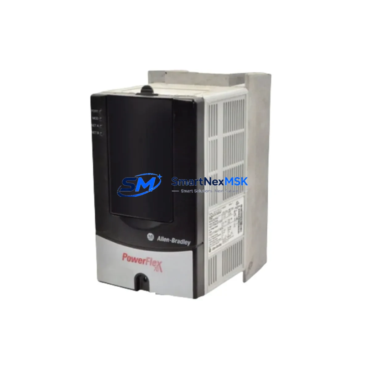
Allen-Bradley 20AD3P4A0AYNNNC0 Spare for PowerFlex 70 Automation
The Allen-Bradley 20AD3P4A0AYNNNC0 is a 2HP (1.5kW), 480V three-phase AC variable frequency drive from the PowerFlex 70 series — one of Rockwell Automation’s most widely deployed drive platforms in discrete manufacturing, material handling, pump control, and conveyor automation. When this unit fails or reaches end-of-service life, unplanned downtime can cascade across an entire production line. Sourcing a maintenance-ready original spare is the fastest path to restoring operation without re-engineering the control architecture.
At SMARTNEXMSK, every 20AD3P4A0AYNNNC0 unit is inspected, function-tested, and shipped with a 12-month warranty. We maintain long-term inventory of PowerFlex 70 series drives to support both emergency replacement and planned maintenance programs. Whether you are a maintenance engineer executing a scheduled overhaul or a procurement engineer building a critical-spare buffer, we provide verified stock with fast global dispatch.
Spare Maintenance Table
| SKU / Part Number | 20AD3P4A0AYNNNC0 |
| Brand | Allen-Bradley (Rockwell Automation) |
| Series | PowerFlex 70 |
| Output Power | 2 HP / 1.5 kW |
| Input Voltage | 480V AC, 3-Phase |
| Output Current | 3.4 A (nominal) |
| Enclosure | IP20 / Open Type (Frame A) |
| Control Mode | Sensorless Vector / V/Hz |
| Communication | DPI port (compatible with 20-COMM-E, 20-COMM-D adapters) |
| Compatibility | Direct replacement for PowerFlex 70 Frame A, 480V class; cross-compatible with 20AD2P1, 20AD4P2 in same frame family |
| Mounting | Panel / DIN rail, standard PowerFlex 70 footprint |
| Operating Temperature | 0°C to 50°C (derating above 40°C) |
| Application Environment | Conveyors, pumps, fans, compressors, packaging lines, HVAC |
| Maintenance Recommendation | Replace cooling fan and DC bus capacitors every 5–7 years; inspect gate driver board annually in high-cycle applications |
| Warranty | 12 Months — covers manufacturing defects; tested before shipment |
| Origin | USA (Rockwell Automation) |
Maintenance Planning for Continuous Operation
Replacing the 20AD3P4A0AYNNNC0 in a live control cabinet is rarely an isolated task. A thorough maintenance engineer will use the drive replacement as an opportunity to inspect and verify the health of surrounding components in the same electrical circuit and control system.
Begin with the input power section: verify the line reactor or EMC filter upstream of the drive — Allen-Bradley 1321-3R series line reactors are commonly paired with PowerFlex 70 drives to suppress harmonic distortion and protect the drive input bridge. Check fusing on the input side; class J or class CC fuses rated to the drive’s input current are standard. Inspect the main circuit breaker or disconnect for contact wear, especially in high-cycle environments.
On the output side, inspect motor cable insulation and verify cable length does not exceed the drive’s rated output without a dV/dt filter. If a 20-OIM-C0 or 20-HIM-A6 HMI keypad is mounted on the drive, confirm the display is functional and parameter sets are backed up before swapping the drive — parameter loss is a common cause of extended commissioning time after replacement.
For communication and network integrity, if the drive is connected via DeviceNet or EtherNet/IP using a 20-COMM-D or 20-COMM-E communication adapter, verify the adapter firmware version is compatible with the replacement drive’s firmware. Mismatched firmware between the drive and communication adapter is a known source of fault codes after replacement.
In the same control cabinet, inspect the Allen-Bradley 1756 ControlLogix or 1769 CompactLogix I/O modules that issue speed reference and enable signals to the drive. Verify analog output signal integrity from the AO module — a degraded 4–20 mA signal can cause erratic speed control that is often misdiagnosed as a drive fault. Check 1492 terminal blocks and wiring ferrules on the control wiring harness for corrosion or loose terminations.
If the system uses a safety relay or safety I/O module (such as the Allen-Bradley 440R Guardmaster series) for drive enable/disable, test the safety circuit continuity before and after drive replacement. Also inspect any signal isolators on the speed reference input — degraded isolation can introduce ground loops that cause nuisance faults. Finally, verify the 24VDC control power supply (commonly a 1606-XLP or similar) is within voltage tolerance, as low control voltage is a frequent but overlooked cause of drive startup failures.
Site Replacement Workflow
Step 1 — Parameter Backup: Before powering down the existing drive, use RSLogix 5000 / Studio 5000 or the HIM keypad to export all drive parameters. Store the parameter file in your CMMS or maintenance records system. This eliminates re-commissioning time and ensures the replacement drive mirrors the original configuration exactly.
Step 2 — Safe Isolation: Follow LOTO (Lockout/Tagout) procedures. Disconnect input power and wait a minimum of 5 minutes for DC bus capacitors to discharge before opening the drive enclosure. Verify bus voltage with a calibrated meter before touching internal components.
Step 3 — Physical Swap: The 20AD3P4A0AYNNNC0 uses the standard PowerFlex 70 Frame A footprint. Disconnect input (R/L1, S/L2, T/L3), output (U/T1, V/T2, W/T3), control wiring, and the DPI communication cable. Mount the replacement unit, reconnect all wiring in reverse order, and torque terminals to specification.
Step 4 — Parameter Restore and Commissioning: Upload the saved parameter file to the replacement drive. Perform a no-load test run at low speed before connecting the motor load. Verify speed reference tracking, acceleration/deceleration ramps, and fault history is clear.
Step 5 — System Verification: Restore the safety circuit, confirm communication adapter status on the network, and run the process at full load for a minimum of 30 minutes before returning the line to production. Document the replacement in your maintenance log with the new unit’s serial number and warranty start date.
This workflow minimizes downtime to under 2 hours for a trained technician and eliminates the risk of parameter-related faults that extend commissioning time.
Spare Parts Support FAQ
Q1: Is the 20AD3P4A0AYNNNC0 a direct drop-in replacement for my existing PowerFlex 70 unit?
Yes. The 20AD3P4A0AYNNNC0 is a standard catalog number within the PowerFlex 70 Frame A, 480V family. It uses the same mounting footprint, terminal layout, and DPI communication interface as all other PowerFlex 70 Frame A drives. No mechanical or wiring modifications are required. Parameter configuration must be restored from your backup file or re-entered manually.
Q2: How do you verify the unit before shipment?
Every unit undergoes a pre-shipment functional test including power-on self-test, DC bus charge verification, output phase balance check, and communication port integrity test. Units that do not pass all checks are not shipped. A test report is available upon request for critical applications.
Q3: What is covered under the 12-month warranty?
The 12-month warranty covers manufacturing defects, component failures under normal operating conditions, and DOA (dead-on-arrival) units. It does not cover damage caused by incorrect installation, overvoltage events, water ingress, or operation outside the rated specifications. Warranty claims are processed within 5 business days of receiving the returned unit.
Q4: Can you support long-term or blanket spare parts orders for our maintenance program?
Yes. SMARTNEXMSK supports planned maintenance programs with reserved stock agreements, scheduled delivery, and multi-unit pricing for PowerFlex 70 series drives and associated components. Contact our sales team to discuss your annual maintenance volume and we will structure a supply agreement that ensures availability without tying up your capital in excess inventory.
© 2026 SMARTNEXMSK. All rights reserved.
Original Source: https://smartnexmsk.com
Contact: sales@smartnexmsk.com | +86 18259474341


