Allen-Bradley 74101-954-53 Retrofit-Ready Gate Driver for 1336 PLUS Control Systems
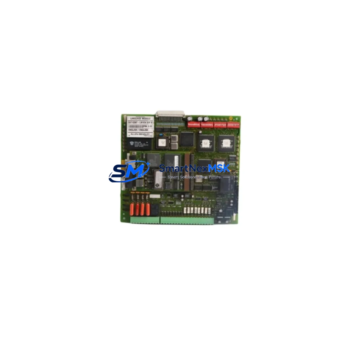
The Allen-Bradley 74101-954-53, also catalogued as 1336T-GT3EN, is a gate driver interface board engineered for the 1336 PLUS and 1336 PLUS II family of AC variable-frequency drives. As Rockwell Automation has progressively discontinued legacy 1336-series components, sourcing a verified replacement for this board has become a critical bottleneck for maintenance engineers managing aging production lines. SMARTNEXMSK maintains ready stock of the 74101-954-53 to support planned retrofit projects and emergency breakdown recovery, backed by a 12-month warranty and pre-shipment functional testing.
Whether you are upgrading a standalone conveyor drive, replacing a failed board in a multi-drive control cabinet, or migrating an entire 1336 PLUS installation to a modernized control architecture, the 74101-954-53 provides a direct, hardware-compatible path that avoids the cost and downtime of a full drive replacement. Each unit is inspected against original Rockwell Automation specifications before dispatch.
Upgrade Compatibility Table
| Parameter | Details |
|---|---|
| Part Number | 74101-954-53 (1336T-GT3EN) |
| Compatible Drive Series | Allen-Bradley 1336 PLUS, 1336 PLUS II |
| Board Function | Gate Driver Interface — IGBT firing signal conditioning |
| Mounting / Installation | Direct board-level replacement; matches original PCB footprint and connector layout |
| Backplane Interface | Compatible with standard 1336 PLUS power structure backplane connectors |
| Communication Compatibility | Supports existing 1336 PLUS control board communication (1336-MOD-series option cards retained) |
| Replacement Recommendation | Suitable for direct swap; verify firmware revision on main control board (1336-BRF-series) before installation |
| Commissioning Notes | Re-run drive autotune after board replacement; verify IGBT gate signals with oscilloscope before energizing motor load |
| Warranty | 12 Months — covers manufacturing defects and functional failure under normal operating conditions |
Retrofit Planning for Existing Automation Systems
A successful retrofit of the 74101-954-53 begins well before the replacement board arrives on site. Maintenance teams should first audit the full 1336 PLUS drive assembly to identify any additional components that may be approaching end-of-life. In many aging installations, the 1336-BRF-SP2 main control board, the 1336-MOD-L2E DeviceNet communication option card, and the 1336-PB-SP2 power board are found alongside the gate driver board in the same control cabinet. Replacing only the failed gate driver while leaving a degraded power board in service is a common cause of repeat failures within 6–12 months.
Terminal wiring on the 1336 PLUS is well-documented in Rockwell publication 1336 PLUS-5.0, but field engineers frequently encounter non-standard wiring modifications made during original commissioning. Before removing the 74101-954-53, photograph all terminal connections and record wire labels. Pay particular attention to the TB1 and TB3 terminal blocks, which carry analog reference signals and digital I/O from the upstream PLC — typically a 1747-L553 SLC 5/05 or a 1756-L71 ControlLogix controller in modernized installations.
If the retrofit is part of a broader control system upgrade, engineers often take the opportunity to migrate I/O from legacy 1746-series SLC I/O modules to 1756-IB16 and 1756-OB16 ControlLogix I/O modules, consolidating the control architecture onto a single 1756-A10 chassis. In these scenarios, the 1336 PLUS drive is typically retained as the power conversion stage while the control layer is modernized, making the 74101-954-53 a cost-effective bridge component that extends drive service life by 5–10 years without requiring a full PowerFlex 755 migration.
For installations that include a PanelView 600 or PanelView Plus 700 HMI, verify that drive status tags mapped to the 1336 PLUS — such as output frequency, DC bus voltage, and fault codes — remain correctly addressed after the board swap. HMI screen logic referencing drive parameters via DH+ or DF1 protocol should be validated in offline simulation before the maintenance window begins. If the site is migrating from DH+ to EtherNet/IP, a 1761-NET-ENI serial-to-Ethernet adapter can bridge the existing 1336 PLUS RS-232 port to the plant network without requiring a drive replacement.
Downtime Control During System Migration
Minimizing unplanned downtime during a 74101-954-53 board replacement requires a structured pre-outage preparation protocol. Begin by uploading the current PLC program from the 1747-L553 SLC or 1756-L71 ControlLogix controller to an offline backup — never rely solely on the program stored in the processor. If the drive is controlled via a 1336-MOD-L2E DeviceNet card, export the DeviceNet network configuration from RSNetWorx for DeviceNet before the outage window opens.
During the board swap, keep the 1336 PLUS drive de-energized at the MCC level and verify zero-voltage at the DC bus capacitors using a calibrated meter before touching any internal components. The gate driver board replacement itself typically takes 20–40 minutes for an experienced technician. After reinstallation, perform a no-load power-up test with the motor disconnected at the T1/T2/T3 output terminals, confirm that the drive displays no fault codes, and then reconnect the motor load for a controlled ramp-up test at 10 Hz before returning to full-speed operation.
For critical production lines where even a 2-hour outage is unacceptable, SMARTNEXMSK recommends maintaining a pre-tested spare 74101-954-53 on-site. Our pre-shipment testing protocol verifies gate signal output waveforms, isolation resistance, and board-level power supply rails before dispatch, so your spare is ready to install immediately when needed. All units ship with a test report and 12-month warranty documentation.
Retrofit Support FAQ
Q1: Is the 74101-954-53 a direct drop-in replacement for the original 1336T-GT3EN gate driver board?
Yes. The 74101-954-53 and 1336T-GT3EN are the same component — the former is the Rockwell Automation internal part number and the latter is the catalog reference used in field service documentation. The board uses the same PCB footprint, connector positions, and signal interface as the original factory-installed unit. No wiring modifications or firmware changes are required on the main 1336-BRF control board.
Q2: What commissioning steps are required after installing the replacement board?
After installation, re-run the drive autotune routine via DriveExplorer or DriveExecutive software connected through the 1336 PLUS RS-232 port. Verify that IGBT gate firing signals are symmetrical across all six gate channels using an oscilloscope before connecting the motor load. Check that the drive fault log is clear and that output current readings match the motor nameplate during a no-load test run.
Q3: Can this board be used in a 1336 PLUS II drive, and are there any hardware revision compatibility issues?
The 74101-954-53 is compatible with both the 1336 PLUS and 1336 PLUS II power structures. However, confirm the drive’s power structure series letter (A, B, or C) against the board revision marking before installation. SMARTNEXMSK technical support can assist with revision matching if you provide the drive nameplate data and existing board revision number.
Q4: What does the 12-month warranty cover, and what is the return process if the board fails?
The 12-month warranty covers manufacturing defects and functional failure under normal operating conditions, including gate signal failure, PCB trace defects, and component-level failures not caused by overvoltage, incorrect installation, or physical damage. To initiate a warranty claim, contact sales@smartnexmsk.com with your order number, a description of the fault symptom, and the drive fault code displayed. Replacement units are dispatched within 2 business days of claim approval.
© 2026 SMARTNEXMSK. All rights reserved.
Original Source: https://smartnexmsk.com
Contact: sales@smartnexmsk.com | +86 18259474341


