Allen-Bradley 80190-100-01-R Retrofit Fiber Optic 1336 PLUS: Compatible Modernization & Smooth System Upgrade
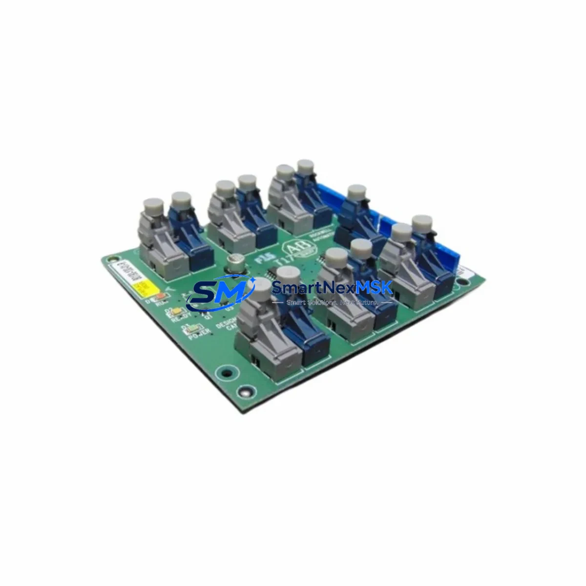
The Allen-Bradley 80190-100-01-R is a fiber optic interface board engineered for the 1336 PLUS family of AC variable-frequency drives. As legacy 1336 PLUS installations approach end-of-support milestones, this board serves as a verified drop-in replacement and retrofit solution for facilities managing aging control architectures. Whether you are restoring a failed drive communication link, upgrading a control cabinet, or migrating an entire production line to a more maintainable platform, the 80190-100-01-R provides the electrical and optical compatibility required to maintain system continuity with minimal disruption.
This interface board supports the fiber optic communication channel used by the 1336 PLUS drive to interface with remote I/O adapters, DeviceNet scanners, and DH+ network bridges. In retrofit scenarios, engineers must verify that the replacement board matches the original slot position on the drive’s internal backplane, that the fiber optic cable type (plastic or glass) is compatible with the installed transceiver, and that the drive firmware version supports the board’s communication protocol revision. All units supplied by SMARTNEXMSK are tested prior to shipment and covered by a 12-month warranty.
Upgrade Compatibility Table
| Parameter | Details |
|---|---|
| Compatible Drive Series | Allen-Bradley 1336 PLUS, 1336 PLUS II |
| Board Function | Fiber Optic Communication Interface |
| Slot / Installation | Internal option slot on 1336 PLUS drive chassis |
| Communication Protocol | Remote I/O (RIO), DH+ via fiber optic link |
| Fiber Cable Type | Plastic fiber optic (verify with installed cable) |
| Replacement Compatibility | Direct replacement for original 80190-100-01-R OEM board |
| Retrofit Recommendation | Verify drive firmware version before installation |
| Commissioning Note | Re-configure node address and baud rate after swap |
| Pre-Shipment Testing | Function-tested before dispatch |
| Warranty | 12 Months |
Retrofit Planning for Existing Automation Systems
Replacing the 80190-100-01-R in an operational plant requires a structured approach that accounts for the full scope of the 1336 PLUS drive’s integration within the control system. In most legacy installations, the 1336 PLUS communicates with a PLC-5 or SLC 500 processor via a Remote I/O scanner module such as the 1771-ASB or 1747-SN. The fiber optic link carries I/O data between the drive and the scanner, and any interruption to this link will cause the processor to fault the I/O rack. Before removing the board, engineers should document the existing node address, baud rate setting, and rack/group/slot assignment configured in the RSLogix 5 or RSLogix 500 program.
In control cabinets where the 1336 PLUS is mounted alongside a 1336 IMPACT or 1336 FORCE drive, the fiber optic ring topology must be maintained. Removing one node without bridging the ring will drop all downstream devices. A temporary fiber optic bypass jumper between the upstream and downstream ports of the affected drive can preserve ring continuity during the board swap. After installing the 80190-100-01-R, the node address DIP switches on the board must be set to match the original configuration before powering the drive.
For facilities transitioning from 1336 PLUS to PowerFlex 700 or PowerFlex 40 drives, the 80190-100-01-R can serve as an interim solution to keep the existing RIO network operational while the migration is planned in phases. The 20-COMM-R Remote I/O adapter for PowerFlex drives provides a parallel migration path, allowing the new drive to join the same RIO network without requiring immediate PLC program changes. During this transition, the 1336-GM1 gateway module and 1336-BDB bus interface board may also require inspection or replacement if they have been in service for more than ten years.
Power supply capacity is a critical verification point in any retrofit. The 1336 PLUS internal power supply must be able to support the option board’s current draw. If the drive is already loaded with a 1336-L3 encoder feedback board or a 1336-GM6 DeviceNet adapter, the additional load of the fiber optic board must be within the drive’s option board power budget. Refer to the 1336 PLUS User Manual (publication 1336 PLUS-5.0) for the option board power allocation table.
Terminal wiring on the drive’s control terminal strip should be photographed and documented before any work begins. The 1336 PLUS uses a standard 24-terminal control wiring block, and any changes to the analog reference input, digital input assignments, or fault relay wiring during the retrofit can introduce commissioning delays. A pre-tested 80190-100-01-R board from SMARTNEXMSK reduces the risk of introducing a second fault variable during the swap.
Downtime Control During System Migration
Minimizing unplanned downtime during a fiber optic board replacement on a 1336 PLUS drive requires preparation at three levels: program backup, hardware staging, and communication verification. Before the maintenance window begins, the RSLogix 5 or RSLogix 500 program should be uploaded from the PLC-5 or SLC 500 processor and saved to a secure location. If the processor uses battery-backed RAM, verify the battery condition using the processor’s status indicator before the outage.
Hardware staging means having the replacement 80190-100-01-R board, the correct fiber optic cables, and any required tools available at the work site before the drive is de-energized. The 1336 PLUS must be powered down and the DC bus voltage verified to be below 50V before the option slot cover is removed. This typically requires a minimum of five minutes after disconnecting the AC input.
After installing the board and restoring power, the drive’s HIM (Human Interface Module), such as the 1336-MOD-L6 or 1336-MOD-L7, should be used to verify that the drive recognizes the fiber optic board in the option slot. The drive’s fault queue should be cleared before placing the drive back online. The PLC processor should then be placed in RUN mode and the I/O status of the 1336 PLUS rack address verified in the RSLogix I/O tree before resuming production. This structured sequence protects the original program logic and ensures that field control continuity is restored without introducing new faults.
Retrofit Support FAQ
Q1: Is the 80190-100-01-R a direct replacement for the original Allen-Bradley board?
Yes. The 80190-100-01-R supplied by SMARTNEXMSK is a verified replacement for the original OEM board used in 1336 PLUS and 1336 PLUS II drives. The board matches the original form factor, connector type, and communication protocol. No drive firmware modification is required for standard installations.
Q2: What commissioning steps are required after installing the replacement board?
After installation, set the node address DIP switches on the board to match the original configuration. Power up the drive and use the HIM to confirm the board is recognized in the option slot. Verify the RIO network status from the PLC scanner module and clear any drive fault codes before returning the system to automatic operation.
Q3: Can this board be used during a migration from 1336 PLUS to a PowerFlex platform?
Yes. The 80190-100-01-R can maintain the existing RIO network during a phased migration. It allows the 1336 PLUS to remain operational on the current network while PowerFlex drives with 20-COMM-R adapters are introduced in parallel, enabling a controlled cutover without requiring simultaneous replacement of all drives.
Q4: What does the 12-month warranty cover?
The 12-month warranty covers manufacturing defects and functional failures under normal operating conditions. All boards are function-tested before shipment. If a board fails within the warranty period under normal use, SMARTNEXMSK will provide a replacement unit. Warranty claims should be submitted to sales@smartnexmsk.com with the order reference and a description of the fault.
© 2026 SMARTNEXMSK. All rights reserved.
Original Source: https://smartnexmsk.com
Contact: sales@smartnexmsk.com | +86 18259474341


