Allen-Bradley 80190-378-51-09 Spare for 800 Series Automation: Backup-Ready PCB for Industrial Downtime Control
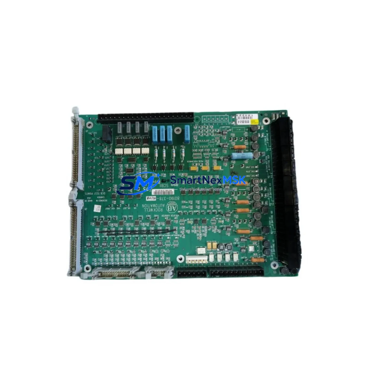
The Allen-Bradley 80190-378-51-09 is an original printed circuit board assembly designed for use within Rockwell Automation 800 Series control architectures. In industrial environments where unplanned downtime translates directly into production loss, having a verified, tested spare of this PCB on hand is a fundamental element of any proactive maintenance strategy. This board serves as a critical signal processing and control interface component within the control cabinet, and its failure — whether from electrical surge, thermal stress, or component aging — can halt an entire automation line.
At SMARTNEXMSK, every unit of the 80190-378-51-09 is sourced from verified supply channels, inspected against original Allen-Bradley specifications, and function-tested prior to dispatch. We support maintenance engineers and procurement teams who need reliable, fast-turnaround spare parts with documented compatibility and a 12-month warranty.
Spare Maintenance Table
| SKU / Part Number | 80190-378-51-09 |
| Brand | Allen-Bradley / Rockwell Automation |
| Product Type | Printed Circuit Board Assembly (PCBA) |
| Compatible Series | Allen-Bradley 800 Series Control Systems |
| Application | Industrial automation control cabinet, signal interface, logic processing |
| Origin | USA (Original Allen-Bradley manufacture) |
| Mounting / Installation | Panel-mount PCB; follow OEM torque and ESD handling specifications |
| Operating Environment | Industrial control cabinet; standard IEC 60068 environmental ratings apply |
| Compatibility Verification | Cross-reference with existing board revision and firmware version before installation |
| Pre-shipment Testing | Function-tested and inspected against OEM specifications |
| Warranty | 12 Months from date of shipment |
| Lead Time | In-stock units ship within 1–3 business days |
| Maintenance Recommendation | Replace at first sign of intermittent faults, communication errors, or thermal discoloration |
Maintenance Planning for Continuous Operation
When a maintenance or procurement engineer identifies the 80190-378-51-09 as a replacement need, the replacement event should be treated as a broader cabinet inspection opportunity. This PCB does not operate in isolation — it interfaces with upstream power supply modules, downstream I/O racks, and communication backplanes that may themselves be approaching end-of-service life.
During a planned or emergency replacement of this board, engineers should simultaneously inspect the Allen-Bradley 1746 SLC 500 I/O modules connected to the same rack, as shared bus faults can cause cascading PCB failures. The 1606-XLP power supply feeding the control cabinet should be load-tested; an aging or undersized power supply is a common root cause of PCB stress. If the system uses a 1747-L553 SLC 5/05 processor or similar, verify that the processor’s firmware and I/O configuration tables remain intact after the board swap.
Communication integrity should be confirmed via the 1747-SDN DeviceNet Scanner or equivalent network module — a board replacement can sometimes reset node addressing. Terminal blocks and 1492-J series wiring accessories adjacent to the PCB slot should be inspected for loose terminations, oxidation, or thermal damage. If the cabinet includes a 2711P PanelView Plus HMI, verify that screen-to-controller communication re-establishes correctly after the swap.
For systems with analog signal loops, check the 1794-IE8 FLEX I/O analog input module and any inline signal isolators for drift or offset errors that may have been masked by the faulty PCB. Fuse holders and miniature circuit breakers on the 24VDC rail should be tested for continuity. Finally, if the installation includes a 1756 ControlLogix backplane in a hybrid architecture, confirm that the rack’s chassis ground and shield terminations are secure before powering up the replacement board.
Stocking one or two units of the 80190-378-51-09 as a cold spare — alongside the associated power and I/O modules — reduces mean time to repair (MTTR) from days to hours and is strongly recommended for any facility running continuous or semi-continuous production.
Site Replacement Workflow
Step 1 — Isolation: De-energize the control cabinet following LOTO (Lockout/Tagout) procedures. Confirm zero-energy state on all rails before opening the enclosure.
Step 2 — Documentation: Photograph the existing board orientation, wiring harness routing, and connector positions. Note the board revision label and any DIP switch or jumper settings.
Step 3 — Removal: Disconnect all connectors in sequence. Remove mounting hardware using ESD-safe tools. Place the faulty board in an anti-static bag for failure analysis or return.
Step 4 — Inspection: Before installing the 80190-378-51-09 replacement, inspect the card slot, backplane connector pins, and adjacent wiring for damage, corrosion, or foreign material.
Step 5 — Installation: Match DIP switch and jumper settings to the documented configuration of the removed board. Seat the PCB firmly and reconnect all harnesses in reverse removal order.
Step 6 — Power-up and Verification: Restore power in stages. Confirm that the processor recognizes the board, all I/O points report correctly, and no fault codes are active on the HMI or programming terminal.
Step 7 — Functional Test: Run a short operational cycle under supervision before returning the line to full production. Log the replacement in the maintenance management system (CMMS) with date, technician, and board serial number.
This workflow is compatible with legacy 800 Series installations and supports system continuity without requiring firmware upgrades or configuration changes in most standard replacement scenarios.
Spare Parts Support FAQ
Q1: Is the 80190-378-51-09 still available as a new original part, or is it a refurbished unit?
All units supplied by SMARTNEXMSK are original Allen-Bradley manufactured boards sourced from verified industrial supply channels. Each unit is inspected and function-tested before shipment. Refurbished or remanufactured units are clearly identified as such — if not stated, the unit is original.
Q2: How do I confirm compatibility with my existing 800 Series control system before ordering?
Provide your existing board’s full part number, revision letter, and the host system model number to our technical team at sales@smartnexmsk.com. We will cross-reference against our compatibility database and confirm fit before you commit to the order. Compatibility verification is provided at no charge.
Q3: What does the 12-month warranty cover, and what is the return process if the board fails on-site?
The 12-month warranty covers manufacturing defects and functional failures under normal operating conditions. It does not cover damage from incorrect installation, overvoltage, or physical impact. To initiate a warranty claim, contact sales@smartnexmsk.com with your order number, failure description, and photos. We will arrange return shipping and dispatch a replacement unit within 3–5 business days of receiving the faulty board.
Q4: Can SMARTNEXMSK support long-term or blanket purchase orders for this spare part?
Yes. For facilities managing aging Allen-Bradley 800 Series systems, we offer long-term supply agreements and reserved inventory arrangements. This ensures you have guaranteed access to the 80190-378-51-09 even as the part becomes harder to source on the open market. Contact our procurement team to discuss volume pricing and scheduled delivery options.
© 2026 SMARTNEXMSK. All rights reserved.
Original Source: https://smartnexmsk.com
Contact: sales@smartnexmsk.com | +86 18259474341


