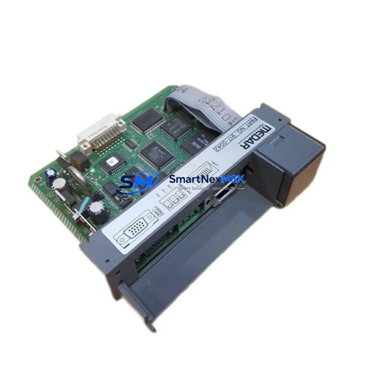
Allen-Bradley 917-0042 Maintenance-Ready Spare for 917 Series Automation
The Allen-Bradley 917-0042 is an original weld control card processor module designed for the 917 Series resistance welding control platform. For maintenance engineers managing aging weld lines or planning scheduled overhauls, having a verified spare of the 917-0042 on hand is a critical element of any downtime-reduction strategy. Unplanned failure of the weld control processor can halt an entire production cell within minutes — sourcing a tested, original-specification replacement in advance is the most effective way to protect uptime and avoid costly emergency procurement.
At SMARTNEXMSK, every 917-0042 unit is inspected, functionally tested, and shipped with a 12-month warranty. We maintain long-term stock of this module to support both emergency replacement and planned maintenance cycles, ensuring your procurement team can secure supply without lead-time risk.
Spare Maintenance Table
| Part Number | 917-0042 |
| Brand | Allen-Bradley |
| Series | 917 Series Weld Control |
| Product Type | Weld Control Card / Processor Module |
| Compatibility | Allen-Bradley 917 Series resistance welding controllers |
| Origin | USA (Original OEM) |
| Weight | 3,400 g (approx.) |
| Application Environment | Industrial weld control cabinets, automotive body shop lines, resistance spot welding cells |
| Installation | Direct plug-in replacement for existing 917-0042 in 917 Series chassis; verify firmware revision before swap |
| Maintenance Recommendation | Inspect connector pins, verify weld schedule parameters post-installation, confirm I/O signal integrity |
| Condition | Original, tested, inspected |
| Warranty | 12 Months |
| Shipping | Worldwide express; anti-static packaging |
Maintenance Planning for Continuous Operation
When a 917-0042 weld control processor is flagged for replacement during a planned shutdown or emergency callout, experienced maintenance engineers know that the module rarely fails in isolation. A thorough site inspection should extend to the entire weld control cabinet and associated electrical circuit to prevent repeat failures and ensure a clean restart.
Begin by auditing the 917 Series power supply module that feeds the control card — voltage sags or ripple are a common root cause of processor faults. Check the weld transformer secondary circuit and associated SCR firing board (such as the 917-0040 or 917-0041 thyristor trigger card) for signs of thermal stress or carbon tracking. Inspect all terminal blocks and wiring harnesses within the cabinet for loose crimps or insulation breakdown, particularly on the high-current secondary side.
On the signal side, verify the integrity of the weld schedule selector switch and any PLC I/O interface card that communicates weld initiation signals to the 917 controller — a degraded I/O module can cause intermittent weld faults that are misdiagnosed as processor failures. If the system uses a DeviceNet or DH-485 communication card for network integration, inspect the cable termination resistors and connector seating. For systems with a current feedback toroid or weld current transducer, confirm the sensor output is within calibration range before commissioning the new 917-0042.
Procurement engineers building a spare parts kit around the 917 Series platform should also consider stocking the 917-0043 weld timer module, 917-0044 contactor interface board, and a set of replacement fuses rated for the weld control bus. For facilities running multiple weld cells, a single spare 917-0042 processor card combined with a documented swap procedure can reduce mean time to repair (MTTR) from hours to under 30 minutes.
Site Replacement Workflow
Step 1 — Isolation: De-energize the weld control cabinet following your site LOTO procedure. Confirm zero energy state on both the control voltage (typically 24 VDC) and weld power bus before opening the enclosure.
Step 2 — Documentation: Photograph the existing 917-0042 connector positions, weld schedule DIP switch settings, and any jumper configurations before removal. This is critical for restoring the exact operating parameters on the replacement unit.
Step 3 — Module Removal: Release the card retaining latch, disconnect all edge connectors and ribbon cables in sequence, and extract the 917-0042 from the chassis slot. Handle by the card frame only — avoid contact with PCB components.
Step 4 — Inspection & Comparison: Compare the replacement 917-0042 firmware label and hardware revision with the removed unit. If revisions differ, consult the 917 Series release notes or contact your controls engineer before proceeding.
Step 5 — Installation: Seat the replacement module firmly into the chassis, reconnect all cables in reverse removal order, and restore DIP switch and jumper settings to match your documentation.
Step 6 — Commissioning: Re-energize the cabinet, verify control power LED status, and run a dry-cycle weld sequence (no current) to confirm I/O handshaking and schedule selection before returning the cell to production.
This structured workflow minimizes re-work risk and supports a clean return-to-service record for your maintenance log. SMARTNEXMSK ships every 917-0042 with a test report, enabling your team to validate the unit against known-good parameters before installation.
Spare Parts Support FAQ
Q1: Is the 917-0042 still available as a new original part, or is it a refurbished unit?
SMARTNEXMSK supplies original Allen-Bradley 917-0042 modules. Each unit undergoes functional testing and inspection prior to shipment. A 12-month warranty is included with every order, covering defects in materials and workmanship under normal operating conditions.
Q2: How do I confirm compatibility before ordering?
Provide your existing 917-0042 hardware revision and the 917 Series controller model number when placing your inquiry. Our technical team will cross-reference your system configuration and confirm compatibility — including any firmware or jumper differences — before the order is processed.
Q3: What is the typical lead time, and can I order multiple units for stock?
In-stock units ship within 1–3 business days via express courier with anti-static packaging. We support bulk procurement for maintenance stock programs and can provide a long-term supply agreement for facilities with recurring 917 Series maintenance requirements.
Q4: What testing is performed before shipment?
Every 917-0042 is powered up and functionally tested against Allen-Bradley 917 Series specifications. A test report is included with shipment. Units that do not pass functional verification are not offered for sale. This process ensures your team receives a field-ready spare, not a cosmetically inspected shelf pull.
© 2026 SMARTNEXMSK. All rights reserved.
Original Source: https://smartnexmsk.com
Contact: sales@smartnexmsk.com | +86 18259474341


