Allen-Bradley EC6682 Retrofit-Ready Axial Monitor for MPS Systems: Compatible Modernization & Smooth Legacy Upgrade
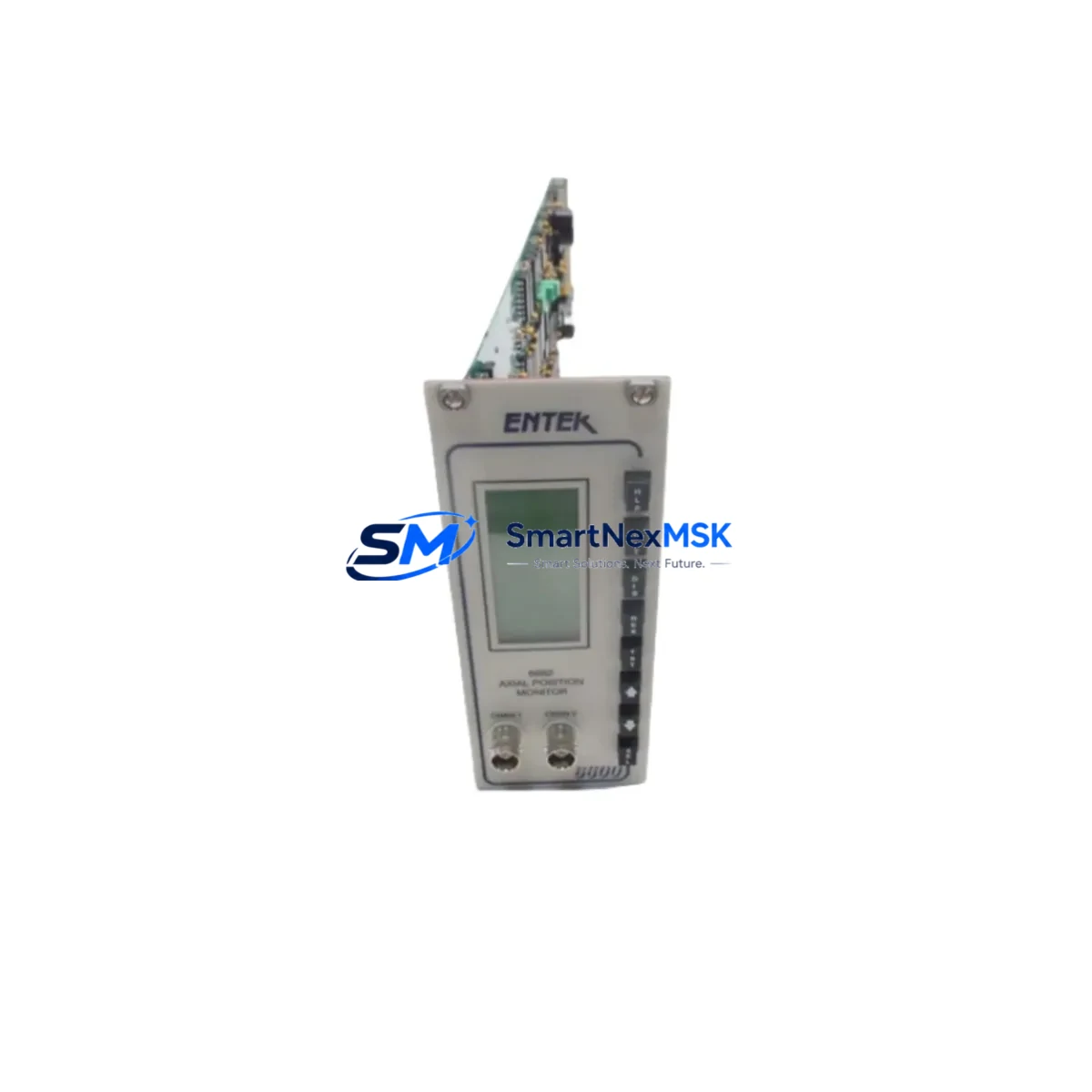
The Allen-Bradley EC6682 is a precision Axial Position Monitor Module designed for use within the Machinery Protection System (MPS) platform. As industrial facilities face increasing pressure to extend the operational life of legacy rotating machinery protection systems, the EC6682 has become a critical retrofit and replacement component for engineers managing turbine trains, compressor skids, and large motor-driven equipment. Whether you are replacing a failed unit, upgrading an aging MPS rack, or migrating from an earlier-generation monitor to a current-production equivalent, the EC6682 provides a reliable, specification-matched solution with minimal disruption to existing wiring and control architecture.
In retrofit applications, the EC6682 is typically installed into existing 1900/A or compatible MPS monitor racks alongside companion modules such as the 1900/A-RM rack module, 1900/A-PS power supply module, and 1900/A-TB terminal block assemblies. The module accepts standard eddy-current proximity probe signals and interfaces directly with existing Bently Nevada 3300 XL or equivalent transducer chains, making it suitable for sites where probe cabling and junction boxes are already in place. Engineers should verify probe gap voltage, sensitivity (mV/mil), and cable length compensation settings during commissioning to ensure measurement accuracy after module swap.
When planning a retrofit, the first step is to confirm rack backplane compatibility. The EC6682 uses a standard MPS edge-connector interface; however, slot addressing and module ID configuration must be verified against the existing system configuration file before installation. If the site uses a 1900/A-GW gateway module for Modbus RTU or EtherNet/IP communication to a ControlLogix or CompactLogix PLC, the gateway’s channel mapping table must be updated to reflect the new module’s slot assignment. Failure to update the gateway configuration is one of the most common causes of communication loss during MPS module replacement.
Power supply capacity is another critical pre-installation check. The MPS rack’s 1900/A-PS power supply module must have sufficient headroom to support the EC6682’s operating current draw alongside all other installed monitor modules. In racks that are fully populated with vibration, position, and temperature monitors, it is advisable to measure actual rail voltage under load before adding or replacing modules. If rail voltage sag is detected, a supplemental or replacement power supply should be sourced before proceeding with the retrofit.
Terminal wiring on the EC6682 follows the standard MPS convention, with clearly labeled screw-terminal blocks for probe positive, probe negative, and shield connections. In most replacement scenarios, existing field wiring can be transferred directly from the failed module to the replacement unit without re-termination, provided that wire labels are verified against the as-built wiring diagram. Where wiring documentation is incomplete or outdated, a point-to-point continuity check is strongly recommended before energizing the new module.
For sites integrating the EC6682 into a broader DCS or safety system architecture, the module’s 4–20 mA analog output and relay contact outputs must be verified against the receiving system’s input card specifications. If the plant DCS uses a Rockwell Automation 1756-IF16 or 1756-IF8 analog input module, signal scaling and engineering unit conversion should be confirmed in the DCS tag database. Similarly, if relay outputs are wired to a safety relay or SIS input card, the contact rating and normally-open/normally-closed configuration must match the original design intent.
HMI screen updates are often overlooked during MPS module replacements. If the facility uses a PanelView Plus or FactoryTalk View SE display to present axial position trends and alarm states, the HMI tag bindings should be reviewed after the module swap to confirm that alarm setpoints, display ranges, and trend historian tags remain correctly mapped. In systems where the MPS gateway communicates via EtherNet/IP to a ControlLogix rack, the Add-On Instruction (AOI) or UDT structure in the PLC program may also require review if the replacement module reports data in a different register format than the original.
Field commissioning of the EC6682 should include a full static calibration check using a calibrated signal simulator, followed by a dynamic verification with the machine at operating speed. Alarm and danger setpoints should be confirmed against the original machinery protection philosophy document, and all relay outputs should be function-tested before the machine is returned to service. A commissioning record documenting probe gap, sensitivity, zero-speed output, and alarm trip levels should be retained for future reference.
SMARTNEXMSK maintains verified stock of the EC6682 and related MPS platform components, including rack assemblies, power supplies, gateway modules, and terminal block accessories. All units are subject to pre-shipment functional testing and are covered by a 12-month warranty against manufacturing defects. Expedited shipping is available for urgent breakdown situations, and our technical team can provide configuration guidance and commissioning support documentation upon request.
Upgrade Compatibility Table
| Parameter | Details |
|---|---|
| Module SKU | EC6682 |
| Brand / Manufacturer | Allen-Bradley / Rockwell Automation |
| Platform / Series | MPS (Machinery Protection System) |
| Module Function | Axial Position Monitor |
| Input Signal Type | Eddy-current proximity probe (standard MPS transducer chain) |
| Analog Output | 4–20 mA (scalable to engineering units) |
| Relay Outputs | Alert and Danger relay contacts (NO/NC configurable) |
| Communication Interface | MPS backplane; gateway-dependent Modbus RTU / EtherNet/IP |
| Rack Compatibility | 1900/A MPS monitor rack (standard edge-connector backplane) |
| Power Supply Compatibility | 1900/A-PS MPS rack power supply module |
| Replacement / Retrofit Path | Direct slot-for-slot replacement in compatible MPS racks |
| Wiring Retention | Yes — existing field wiring transferable (verify labels) |
| Installation Requirement | Slot address and gateway channel map update required |
| Commissioning Requirement | Static calibration + dynamic verification at operating speed |
| Country of Origin | United States |
| Warranty | 12 Months — covers manufacturing defects, pre-shipment tested |
Retrofit Planning for Existing Automation Systems
A successful EC6682 retrofit begins well before the module arrives on site. The engineering team should assemble the existing MPS system documentation, including the rack layout drawing, module address map, gateway configuration file, and the machinery protection philosophy document. In a typical MPS rack, the EC6682 occupies a dedicated monitor slot alongside other channel modules such as radial vibration monitors, speed monitors, and temperature monitors. The 1900/A-RM rack module provides the backplane communication bus, and its firmware version should be noted to confirm compatibility with the replacement EC6682 hardware revision.
The 1900/A-PS power supply module should be load-tested prior to the retrofit, particularly in racks where additional I/O expansion or communication modules have been added since the original installation. If the rack also houses a 1900/A-GW gateway module for upstream PLC or DCS integration, the gateway’s Modbus register map or EtherNet/IP tag table must be exported and backed up before any module changes are made. This backup is essential for rapid recovery if the gateway requires reconfiguration after the swap.
For sites where the MPS system feeds alarm and trip signals to a Rockwell Automation ControlLogix or CompactLogix safety controller, the PLC program logic referencing EC6682 channel data should be reviewed. If the program uses a 1756-IF16 analog input card to receive the module’s 4–20 mA position signal, the input scaling parameters in the PLC tag database must match the EC6682’s configured output range. Where the system includes a PanelView Plus HMI displaying axial position trends, the HMI project file should be backed up and the relevant display pages reviewed for correct tag mapping after the module replacement.
In facilities where the MPS rack communicates via a 1900/A-GW gateway to a FactoryTalk Historian or third-party SCADA system, the historian tag configuration should be verified post-installation to confirm that data collection resumes correctly. Programming cables such as the 1784-U2DHP or standard USB-to-serial adapters may be required for gateway reconfiguration, and the appropriate configuration software version should be confirmed before the maintenance window begins.
Downtime Control During System Migration
Minimizing unplanned downtime during an MPS module replacement requires a structured pre-outage preparation process. Before the maintenance window opens, the engineering team should complete a full backup of the MPS gateway configuration, PLC program, and HMI project. All alarm and danger setpoints should be documented from the existing system, and a copy of the current module configuration (probe type, sensitivity, gap voltage, and alarm levels) should be extracted using the MPS configuration software.
During the replacement window, the affected machine should be brought to a safe, controlled stop in accordance with the site’s machinery protection bypass procedure. The EC6682 slot should be de-energized before module removal, and the existing field wiring should be photographed and labeled before disconnection. The replacement module should be pre-configured off-line where possible, with probe type, sensitivity, and alarm setpoints entered before installation to reduce in-rack configuration time.
After installation, a systematic commissioning sequence — static calibration, relay function test, gateway communication verification, and HMI display confirmation — should be completed before the machine is restarted. Having a pre-prepared commissioning checklist and a spare 1900/A-PS power supply module on hand can further reduce recovery time in the event of an unexpected complication. With proper preparation, an EC6682 slot replacement can typically be completed within a planned maintenance window of two to four hours, preserving production continuity and protecting the integrity of the original control program logic.
Retrofit Support FAQ
Q1: Is the EC6682 a direct drop-in replacement for the original module in my MPS rack?
In most cases, yes. The EC6682 is designed for slot-for-slot installation in compatible 1900/A MPS monitor racks. However, you must verify the rack backplane revision, module slot address assignment, and gateway channel mapping before installation. Pre-configuration of the replacement module off-line is strongly recommended to minimize in-rack commissioning time.
Q2: Can I retain my existing field wiring when replacing the EC6682?
Yes, in the majority of retrofit scenarios existing probe wiring can be transferred directly to the replacement module without re-termination. Verify wire labels against the as-built wiring diagram before transfer, and perform a point-to-point continuity check if documentation is incomplete or outdated.
Q3: What commissioning steps are required after installing the EC6682?
Commissioning should include: (1) static calibration using a signal simulator to verify probe gap voltage and sensitivity; (2) alarm and danger setpoint entry and verification; (3) relay output function test; (4) gateway communication verification (Modbus register or EtherNet/IP tag confirmation); and (5) dynamic verification at operating machine speed. A commissioning record should be retained for future reference.
Q4: What warranty coverage is provided, and has the unit been tested before shipment?
All EC6682 units supplied by SMARTNEXMSK are covered by a 12-month warranty against manufacturing defects. Each unit undergoes pre-shipment functional testing to verify module operation before dispatch. In the event of a warranty claim, our technical team will provide replacement or repair support with priority handling to minimize your system downtime.
© 2026 SMARTNEXMSK. All rights reserved.
Original Source: https://smartnexmsk.com
Contact: sales@smartnexmsk.com | +86 18259474341


