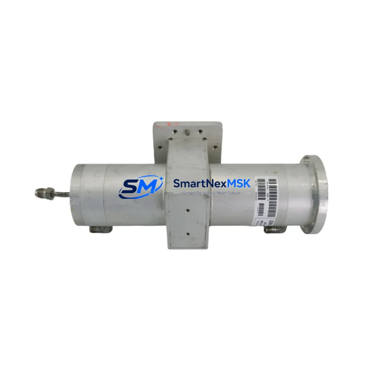
Applied Materials 0020-28293 Retrofit-Ready DGF Enclosure for CVD Control Systems
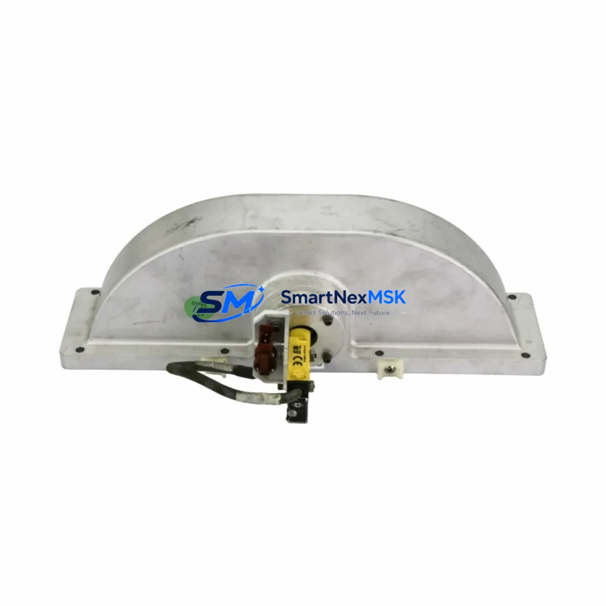
The Applied Materials 0020-28293 DGF (Diffusion Gas Flow) Enclosure Assembly is a retrofit-ready replacement and upgrade solution engineered for Applied Materials CVD (Chemical Vapor Deposition) process platforms. Cross-referenced against part numbers 0020-22879, 17-326448C01, 710-031325-002, and 810-031325-002, this enclosure assembly is sourced, inspected, and shipped to support planned maintenance cycles, emergency line-down recovery, and long-term system modernization programs.
As Applied Materials legacy CVD chambers age into end-of-life support windows, facilities engineering teams and process equipment managers face increasing pressure to source reliable enclosure assemblies that maintain dimensional accuracy, thermal tolerance, and gas-path integrity. The 0020-28293 enclosure is a direct structural and functional replacement for the original OEM assembly, making it suitable for drop-in installation without modification to the chamber body, gas distribution manifold, or RF match network mounting provisions.
This assembly is particularly relevant for retrofit programs involving the Applied Materials Precision 5000, Centura, and Producer platform families, where the DGF enclosure interfaces directly with the process kit, liner assembly, and susceptor support structure. Engineers planning a chamber refurbishment should verify the enclosure’s compatibility with the existing 0010-09764 chamber body and confirm that the gas inlet port geometry aligns with the installed 0040-06858 gas distribution plate. Dimensional verification against the installed 0020-22879 baseline is recommended prior to final installation.
Upgrade Compatibility Table
| Parameter | Details |
|---|---|
| Primary Part Number | 0020-28293 |
| Cross-Reference / Supersedes | 0020-22879 | 17-326448C01 | 710-031325-002 | 810-031325-002 |
| Compatible Platform | Applied Materials CVD — Precision 5000, Centura, Producer Series |
| Assembly Type | DGF (Diffusion Gas Flow) Enclosure Assembly |
| Installation Type | Drop-in retrofit; no chamber body modification required |
| Interface Compatibility | Compatible with OEM gas distribution manifold, liner, and susceptor support |
| Communication / Control | Passive mechanical assembly; integrates with existing process control and MFC network |
| Commissioning Requirement | Leak check, gas flow verification, and process baseline qualification recommended |
| Warranty | 12-Month Warranty from date of shipment |
| Origin | CN — Inspected and tested prior to dispatch |
Retrofit Planning for Existing Automation Systems
A successful DGF enclosure retrofit on an Applied Materials CVD platform requires systematic pre-installation planning across mechanical, process, and control domains. Before removing the legacy 0020-22879 or 810-031325-002 enclosure, the engineering team should document the current process baseline — including deposition rate, uniformity map, and particle count — to establish a post-installation qualification target.
On the mechanical side, confirm that the chamber body flange surfaces are free of contamination and that the existing 0040-06858 gas distribution plate and 0020-09764 liner assembly are within service life. If the liner is approaching its scheduled replacement interval, it is cost-effective to replace it concurrently with the enclosure to avoid a second chamber opening within a short maintenance window. Similarly, inspect the 0040-00082 susceptor and its support pins for wear, as enclosure replacement provides direct access to these components.
On the process control side, verify that the installed mass flow controllers (MFCs) — typically 0190-09986 or equivalent — are calibrated and that the gas panel manifold connections are leak-tight before closing the chamber. The 0020-28293 enclosure does not alter the gas inlet geometry, so existing MFC recipes and flow setpoints remain valid. However, a full leak check using the chamber’s built-in helium or nitrogen leak test routine is mandatory after installation.
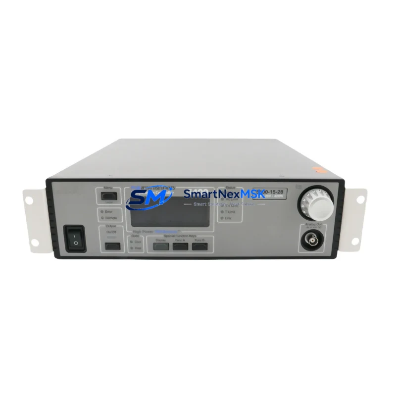
For facilities teams managing multiple chambers on a single CVD cluster tool, it is advisable to stage the retrofit one chamber at a time to maintain partial production capacity. The 0010-09764 chamber body and the associated RF match network — often an 0190-06924 or equivalent unit — should remain undisturbed during the enclosure swap to preserve RF tuning parameters and avoid unnecessary re-qualification of the plasma ignition sequence.
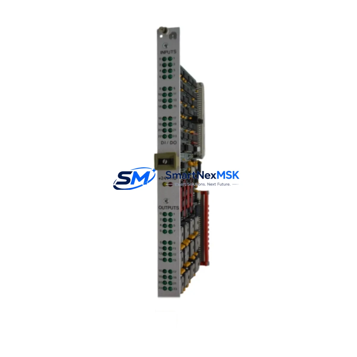
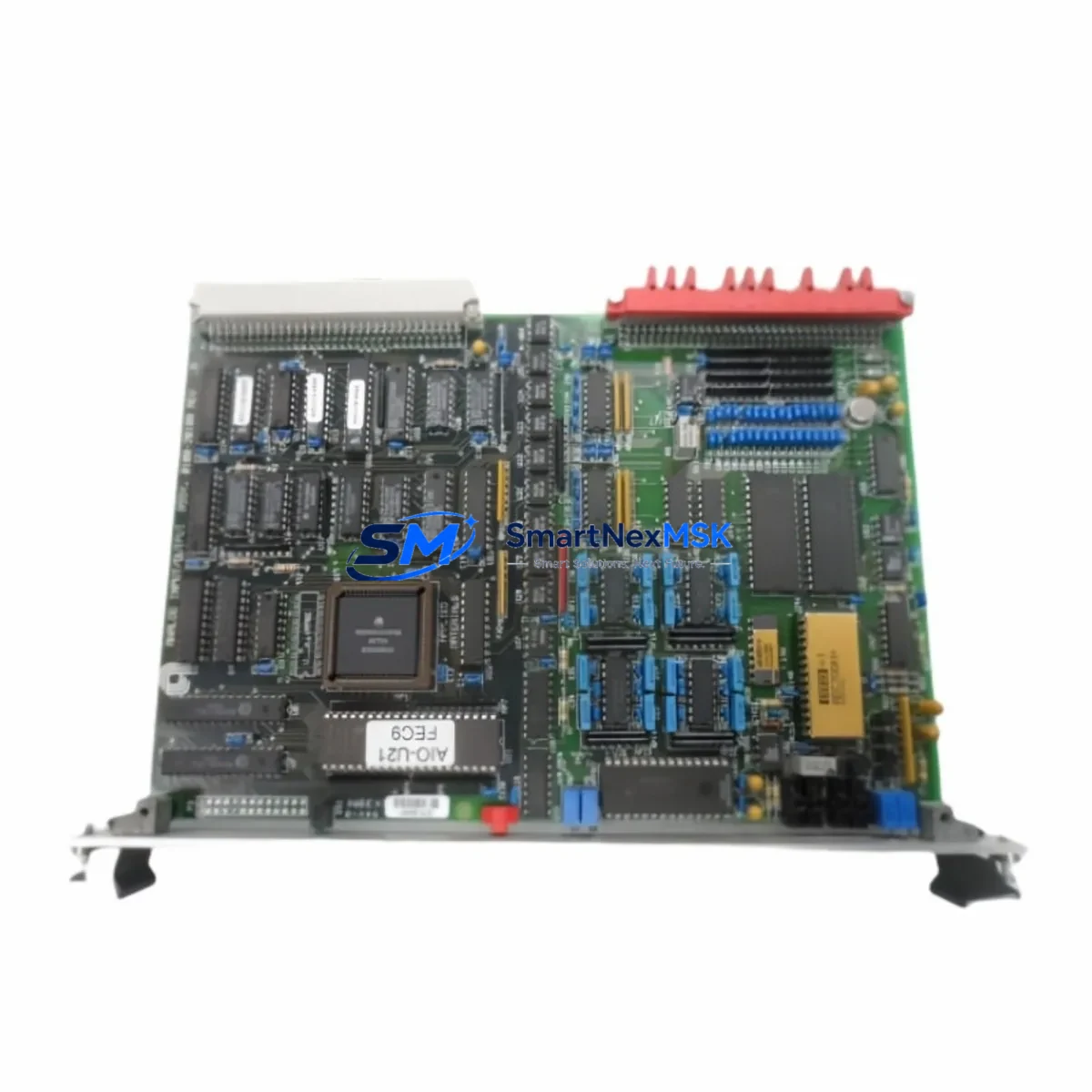
If the retrofit is part of a broader platform upgrade that includes replacing the process controller or upgrading the host software, coordinate the enclosure installation with the controls team to ensure that the chamber identity, recipe library, and alarm setpoints are correctly migrated before the chamber is returned to production. Facilities running legacy 0100-09041 I/O boards or older VME-based control architectures should confirm that the new enclosure’s sensor wiring harness — if applicable — is compatible with the existing terminal block assignments.
Downtime Control During System Migration
Minimizing unplanned downtime during a DGF enclosure replacement is a primary concern for fab operations teams. The 0020-28293 is stocked and available for same-week dispatch, which directly reduces the lead-time component of mean time to repair (MTTR). To further compress downtime, pre-stage all required consumables — including new O-rings, chamber seals, and process kit components — before scheduling the maintenance window.
Preserve the original process program and recipe files on the chamber controller before beginning any hardware work. For chambers running Applied Materials’ proprietary process software, export the active recipe set and store it on a separate backup medium. This ensures that if the controller requires a reboot or software reset during the maintenance cycle, the process logic can be restored without manual re-entry.
Where possible, perform the enclosure swap during a scheduled preventive maintenance (PM) window rather than as an emergency repair. This allows the process team to run a full qualification wafer sequence — including deposition rate, film thickness uniformity, and particle adder tests — before returning the chamber to production. A structured qualification protocol, aligned with the fab’s standard chamber release procedure, ensures that the retrofitted chamber meets process specifications and that the 12-month warranty period begins from a verified baseline.
For multi-chamber cluster tools, maintain at least one chamber in production status throughout the retrofit to sustain wafer throughput. Coordinate with the production scheduler to identify low-utilization periods — typically weekend shifts or planned product changeovers — as the preferred maintenance window for enclosure replacement.
Retrofit Support FAQ
Q1: Is the 0020-28293 a direct drop-in replacement for the 0020-22879 and 810-031325-002?
Yes. The 0020-28293 is cross-referenced against 0020-22879, 17-326448C01, 710-031325-002, and 810-031325-002. It is designed as a dimensional and functional equivalent, requiring no modification to the chamber body or gas distribution manifold. Verify flange surface condition and O-ring groove dimensions before installation.
Q2: What commissioning steps are required after installation?
After mechanical installation, perform a chamber leak check using the platform’s standard nitrogen or helium leak test routine. Verify gas flow paths through the MFC network, confirm that all sensor connections are secure, and run a process qualification sequence using a monitor wafer before returning the chamber to production. Document the post-installation baseline for future reference.
Q3: Does the enclosure replacement affect existing wiring or control connections?
The 0020-28293 is a passive mechanical enclosure assembly. It does not include active electronic components, so existing wiring harnesses, terminal block assignments, and I/O connections remain unchanged. If the chamber includes integrated thermocouple or pressure sensor connections routed through the enclosure, verify connector pinout compatibility against the original assembly drawing before final installation.
Q4: What warranty coverage is provided, and what does it include?
All units are covered by a 12-month warranty from the date of shipment. The warranty covers manufacturing defects and dimensional non-conformance. Each unit is inspected and tested prior to dispatch. For warranty claims or technical support, contact our team directly with the shipment reference number and a description of the observed issue.
© 2026 SMARTNEXMSK. All rights reserved.
Original Source: https://smartnexmsk.com
Contact: sales@smartnexmsk.com | +86 18259474341