Applied Materials 0190-25081 Spare | 23HS24 Automation: Maintenance-Ready Replacement for Industrial Downtime Control
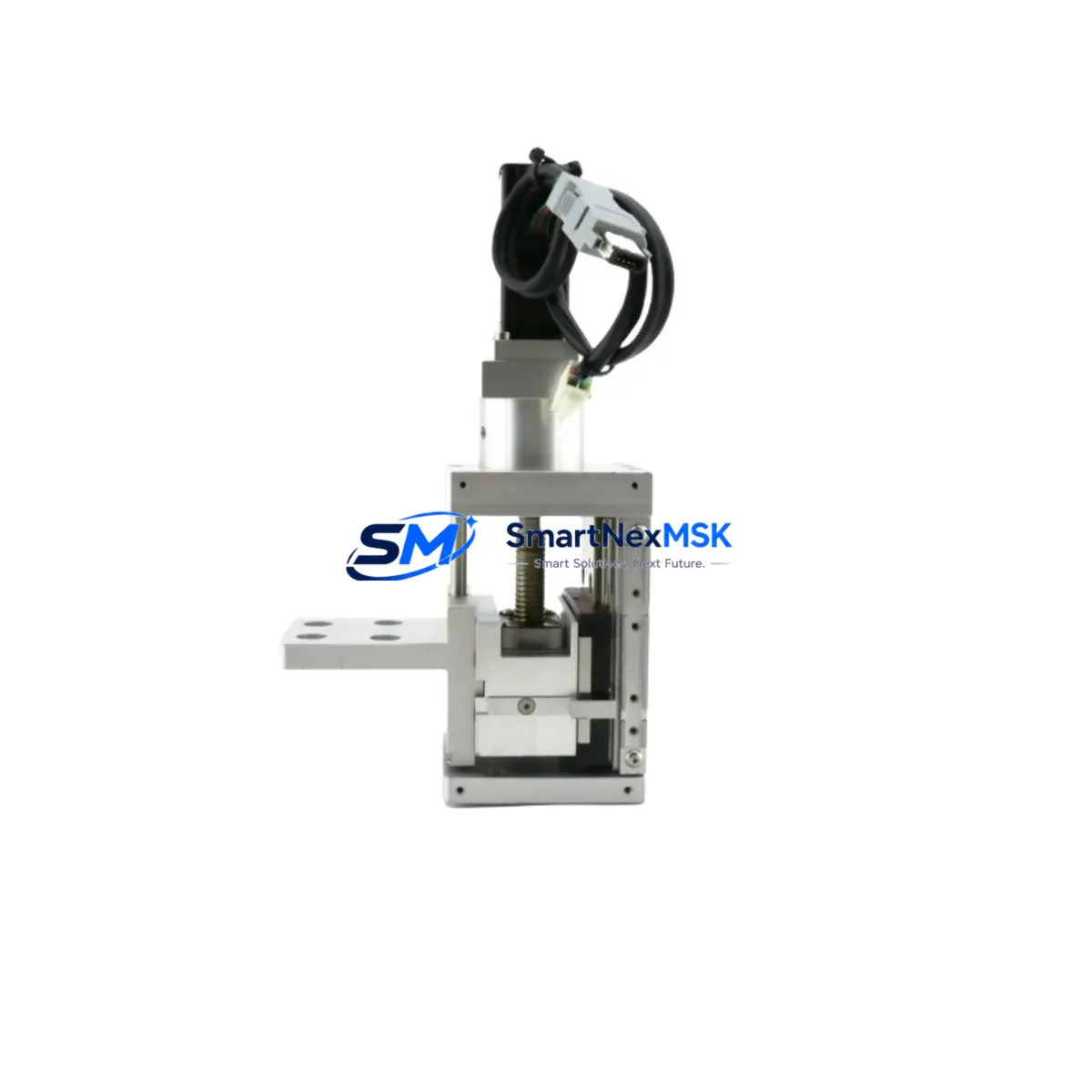
The Applied Materials 0190-25081 is an original-specification stepper linear actuator designed for the 23HS24 series motion control platform, widely deployed in semiconductor wafer handling, precision positioning stages, and automated process equipment. Cross-referenced as 0200-10265 and 23S21-0560-8A5L7-55(30), this NEMA 23 frame actuator delivers the torque, stroke accuracy, and thermal stability required for continuous-duty industrial environments.
For maintenance engineers managing Applied Materials process tools, sourcing a verified 0190-25081 spare is a critical step in any planned or emergency shutdown recovery. Unplanned actuator failure in a wafer transfer module or load-lock positioning stage can result in hours of unscheduled downtime. Keeping a tested, ready-to-install unit in your spare parts cabinet eliminates that risk entirely.
Every unit shipped by SMARTNEXMSK undergoes pre-shipment electrical verification — winding resistance, insulation integrity, and step-response testing — before dispatch. A 12-month warranty covers all units against manufacturing defects and performance deviation from OEM specification.
Spare Maintenance Table
| Parameter | Specification |
|---|---|
| Part Number | 0190-25081 |
| Cross Reference | 0200-10265 / 23S21-0560-8A5L7-55(30) |
| Series | 23HS24 (Applied Materials) |
| Frame Size | NEMA 23 (57 mm) |
| Motor Type | Hybrid Stepper Linear Actuator |
| Step Angle | 1.8° (200 steps/rev) |
| Rated Current | Refer to OEM datasheet (typically 2.0–3.0 A/phase) |
| Lead Screw Pitch | Per 23HS24 series specification |
| Insulation Class | Class B / Class F (application dependent) |
| Operating Temperature | 0°C to +50°C ambient |
| Mounting | NEMA 23 4-bolt face mount |
| Connector Type | 4-wire bipolar / 6-wire unipolar (verify with OEM wiring diagram) |
| Compatibility | Applied Materials 23HS24 series motion assemblies; compatible stepper drivers accepting NEMA 23 bipolar input |
| Application Environment | Semiconductor fab, cleanroom-adjacent, precision automation |
| Maintenance Interval | Inspect every 6–12 months; replace on torque degradation or step-loss events |
| Warranty | 12 Months — covers electrical and mechanical defects |
| Pre-Shipment Test | Winding resistance, insulation, step-response verification |
| Lead Time | In-stock; ships within 1–3 business days |
Maintenance Planning for Continuous Operation
When a 0190-25081 actuator is flagged for replacement during a scheduled PM or after a step-loss fault, experienced maintenance engineers know that the actuator itself is rarely the only component that needs attention. A thorough inspection of the surrounding motion control circuit is essential to prevent repeat failures and ensure the system returns to full specification.
Begin with the stepper motor driver module — typically a dedicated axis card or a standalone driver such as those in the Applied Materials motion controller rack. Verify output current settings match the 0190-25081 winding specification; an over-driven or under-driven actuator will fail prematurely regardless of part quality. Check the 24 VDC logic power supply feeding the driver enable line and confirm voltage is within ±5% tolerance under load.
Inspect the motor cable assembly (often a shielded 4-conductor or 6-conductor harness) for insulation damage, connector pin corrosion, and shield continuity. In semiconductor environments, repeated thermal cycling and chemical exposure can degrade cable jackets faster than the actuator itself. A replacement cable — matched to the 23HS24 series connector pinout — should be stocked alongside the 0190-25081 spare.
Review the home sensor and limit switch assembly associated with the actuator’s travel axis. Optical or magnetic home sensors that have drifted out of alignment will cause positioning errors even after a perfect actuator swap. Similarly, inspect the end-of-travel limit switches and their wiring back to the I/O module.
For systems integrated into a PLC or DCS architecture, verify the pulse/direction signal path from the controller output card to the driver input. Signal integrity issues — ground loops, impedance mismatches, or noise on the step pulse line — can mimic actuator faults. A signal isolator or line driver may be warranted if the cable run exceeds 3 meters.
Check the terminal block connections on the driver output and power input sides. Loose terminals are a leading cause of intermittent actuator faults in high-vibration environments. Torque all terminals to specification and apply anti-vibration locking compound where appropriate.
If the 23HS24 assembly is part of a multi-axis gantry or transfer robot, also inspect the coupling and lead screw assembly for wear, backlash, and lubrication. A worn lead screw nut will cause positioning drift that no actuator replacement can correct. Finally, review the axis alarm history in the HMI or SCADA system — recurring over-current or stall alarms prior to failure often indicate a mechanical binding issue upstream of the actuator.
Site Replacement Workflow
Step 1 — Isolation: De-energize the motion axis at the driver enable input. Lock out the 24 VDC control power and the motor phase power at the terminal block. Confirm zero voltage with a calibrated meter before disconnecting any wiring.
Step 2 — Documentation: Photograph the existing wiring harness routing and connector orientation before removal. Record the current home position offset and axis calibration parameters from the HMI or controller memory. These values will be needed during recommissioning.
Step 3 — Mechanical Removal: Disconnect the motor cable at the nearest accessible connector. Remove the four NEMA 23 face-mount bolts. Carefully extract the 0190-25081 actuator from the linear stage, noting the lead screw engagement depth and anti-rotation pin orientation if present.
Step 4 — Installation: Install the replacement 0190-25081 unit, aligning the lead screw thread engagement to the same depth as the removed unit. Torque mounting bolts evenly in a cross pattern. Reconnect the motor cable, verifying phase wiring matches the original color-code or OEM wiring diagram for the 23HS24 series.
Step 5 — Recommissioning: Restore control power. Perform a slow-speed manual jog to verify direction and home sensor trigger point. Re-enter the saved axis calibration parameters. Run a full-stroke positioning test at 25%, 50%, and 100% speed before returning the system to production.
Step 6 — Documentation Close-Out: Log the replacement in the CMMS with the new unit serial number, installation date, and post-replacement test results. Update the spare parts inventory to trigger reorder of a replacement 0190-25081 unit.
Spare Parts Support FAQ
Q1: Is the 0190-25081 a direct drop-in replacement for the 0200-10265 and 23S21-0560-8A5L7-55(30) part numbers?
Yes. These cross-reference numbers refer to the same 23HS24 series NEMA 23 stepper linear actuator assembly. All three part numbers share the same mechanical envelope, winding specification, and connector pinout. No driver reconfiguration is required when substituting between these references, though we recommend verifying the OEM wiring diagram for your specific tool revision before installation.
Q2: How should the 0190-25081 be stored as a long-term spare?
Store in the original anti-static packaging in a dry environment at 10°C–35°C with relative humidity below 70% (non-condensing). Avoid storage near strong magnetic fields or corrosive atmospheres. For long-term storage exceeding 12 months, rotate the lead screw manually every 6 months to prevent lubricant migration and static friction buildup. Inspect winding insulation resistance annually with a 500 V megohmmeter.
Q3: What pre-shipment testing is performed on each unit?
Every 0190-25081 unit shipped by SMARTNEXMSK is tested for winding resistance (per-phase, balanced within ±5%), insulation resistance (>100 MΩ at 500 VDC), and step-response under no-load conditions. A test report is available upon request. Units that fail any parameter are quarantined and not shipped.
Q4: What does the 12-month warranty cover, and how is a claim processed?
The 12-month warranty covers all electrical and mechanical defects attributable to manufacturing or material quality. It does not cover damage from incorrect installation, over-current operation, or physical impact. To initiate a warranty claim, contact sales@smartnexmsk.com with the order number, unit serial number, and a description of the fault. SMARTNEXMSK will arrange return shipping and provide a replacement or refund within 10 business days of receiving the defective unit.
© 2026 SMARTNEXMSK. All rights reserved.
Original Source: https://smartnexmsk.com
Contact: sales@smartnexmsk.com | +86 18259474341