B&R 5LS182.6-1 Retrofit-Ready CPU for 2005 Control Systems: Compatible Modernization & Smooth Legacy Upgrade
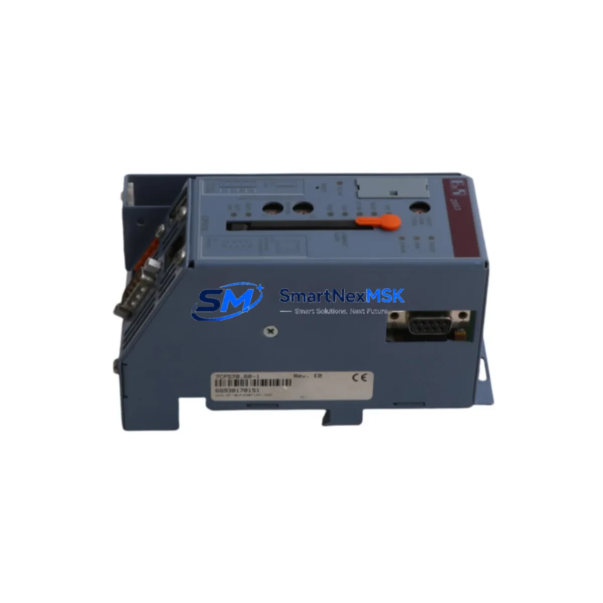
The B&R 5LS182.6-1 is a high-performance CPU module designed for the B&R 2005 System platform — one of the most widely deployed modular PLC architectures in European and Asian industrial facilities. As original equipment reaches end-of-life and OEM support windows close, the 5LS182.6-1 has become a critical retrofit component for engineers tasked with extending the operational life of existing control cabinets without committing to a full platform migration.
Whether you are replacing a failed unit on an active production line, sourcing a verified spare for a scheduled maintenance window, or executing a phased modernization of a legacy automation system, the B&R 5LS182.6-1 delivers the processing capability, backplane compatibility, and communication protocol support required to maintain continuity in demanding industrial environments.
Upgrade Compatibility Table
| Parameter | Details |
|---|---|
| SKU / Part Number | 5LS182.6-1 |
| Brand / Manufacturer | B&R (Bernecker & Rainer), Austria |
| Compatible Platform | B&R 2005 System |
| Module Type | PLC CPU Module |
| Backplane Interface | 2005 System backplane bus (direct slot insertion) |
| Communication Protocol | PROFIBUS-DP, RS-232, proprietary B&R system bus |
| Installation Requirement | Standard 2005 rack/chassis; no mechanical modification required |
| Replacement Compatibility | Direct drop-in for equivalent 2005 System CPU slots |
| Programming Environment | B&R Automation Studio (compatible versions) |
| Commissioning Notes | Verify module address, I/O mapping, and program download before live restart |
| Origin | Austria |
| Warranty | 12-Month Quality Warranty |
Retrofit Planning for Existing Automation Systems
Successful integration of the B&R 5LS182.6-1 into an existing 2005 System installation begins with a thorough pre-replacement audit. Engineers should document the current rack layout, including the positions of all installed modules such as digital I/O cards, analog input modules, and any 2005 System power supply units (e.g., 0PS952.1 or equivalent) that feed the backplane. Confirming that the power supply can sustain the additional current draw of the replacement CPU is a non-negotiable first step — undersized power rails are a common cause of intermittent faults after module swaps.
Terminal wiring on the 2005 System is largely standardized, but field engineers should cross-reference the existing wiring diagram against the 5LS182.6-1 pinout before disconnecting any cables. In installations where the original CPU was connected to a PROFIBUS-DP network, the bus address and baud rate settings must be preserved. Downstream PROFIBUS slaves — including distributed I/O stations, variable frequency drives, and remote HMI panels — will lose synchronization if the master address changes unexpectedly during the swap.
For systems using B&R 2005 communication modules such as the 2DP352.6 PROFIBUS interface card or RS-232 serial adapters, verify that the new CPU firmware version is compatible with the installed communication stack. In multi-rack configurations, the backplane interconnect cables and 2005 System rack expansion modules should be inspected for wear before the new CPU is commissioned — a degraded rack bus can produce erratic behavior that is difficult to distinguish from a CPU fault.
I/O expansion in 2005 System cabinets typically relies on a combination of local digital input/output modules and remote I/O nodes connected via the system bus. When replacing the CPU, re-validate the I/O address table in the project file using B&R Automation Studio. If the original program was compiled against an older hardware configuration, a hardware configuration update may be required before the program can be downloaded to the 5LS182.6-1. Pay particular attention to any analog I/O modules (e.g., 2AO352.6 or 2AI352.6x) whose scaling parameters are stored in the CPU’s non-volatile memory — these values must be re-entered or restored from a backup after the module replacement.
HMI panels connected to the 2005 System — whether legacy B&R Power Panel units or third-party operator terminals communicating via RS-232 or Ethernet — should be tested for screen navigation, alarm acknowledgment, and data write functions after the CPU swap. A common oversight is failing to verify that the HMI’s communication driver timeout settings are compatible with the new CPU’s response latency, which can cause spurious communication error messages on the operator screen.
For facilities managing a mixed fleet of B&R controllers, it is advisable to maintain a parallel inventory of related components including 2005 System programming cables (e.g., 0AC201.9), CompactFlash memory cards for program backup, and spare 2005 System digital output modules to support rapid field recovery during unplanned outages.
Downtime Control During System Migration
Minimizing production downtime during a CPU replacement on a live 2005 System installation requires disciplined pre-staging and a clear rollback plan. Before the maintenance window opens, the replacement B&R 5LS182.6-1 should be bench-tested with a copy of the production program loaded and verified in offline simulation mode using Automation Studio. This confirms that the hardware is functional and that the program compiles without errors against the new module’s firmware baseline.
On the day of the swap, the sequence should follow a defined protocol: first, perform a full program backup from the existing CPU to a CompactFlash card or PC-based project archive. Second, document all current I/O states, setpoints, and communication parameters. Third, power down the rack in the correct sequence — CPU first, then I/O modules, then the power supply — to avoid backplane transients that can corrupt module firmware. After installing the 5LS182.6-1, restore power in reverse order and allow the system bus to initialize fully before attempting a program download.
Once the program is loaded, perform a controlled cold start and monitor the first scan cycle for any I/O faults, communication errors, or unexpected output activations. In process-critical applications, it is strongly recommended to keep the original CPU module on-site as a fallback unit until the replacement has completed at least one full production cycle without fault. This approach limits the blast radius of any unforeseen compatibility issue and allows the maintenance team to restore the original configuration within minutes if needed.
All units supplied by SMARTNEXMSK undergo pre-shipment functional testing and are covered by a 12-month quality warranty, reducing the risk associated with sourcing discontinued or hard-to-find B&R 2005 System components from the secondary market.
Retrofit Support FAQ
Q1: Is the B&R 5LS182.6-1 a direct replacement for the original 2005 System CPU in my cabinet?
A: Yes. The 5LS182.6-1 is designed for direct slot-in replacement within the B&R 2005 System rack. No mechanical modification to the chassis or backplane is required. You will need to download your existing program to the new module and verify I/O addressing and communication parameters before returning the system to production.
Q2: What commissioning steps are required after installing the 5LS182.6-1?
A: After physical installation, connect the programming cable (e.g., 0AC201.9 or USB-to-serial adapter), open the project in B&R Automation Studio, perform a hardware configuration update if prompted, download the program, and execute a controlled cold start. Verify all I/O channels, PROFIBUS slave communication, and HMI connectivity before releasing the system to operators.
Q3: My existing wiring uses the original terminal layout — will I need to re-wire the cabinet?
A: In most standard 2005 System configurations, the terminal wiring connects to I/O modules rather than directly to the CPU, so no re-wiring of field cables is typically required. However, any direct CPU port connections (RS-232, PROFIBUS connector, or system bus cable) should be verified against the 5LS182.6-1 port layout before installation.
Q4: What warranty and testing does SMARTNEXMSK provide with this module?
A: Every B&R 5LS182.6-1 unit shipped by SMARTNEXMSK is covered by a 12-month quality warranty. Pre-shipment testing includes power-on verification and functional checks. In the event of a confirmed defect within the warranty period, we provide replacement or repair support. Contact our technical team at sales@smartnexmsk.com for warranty claims or pre-purchase compatibility consultation.
© 2026 SMARTNEXMSK. All rights reserved.
Original Source: https://smartnexmsk.com
Contact: sales@smartnexmsk.com | +86 18259474341