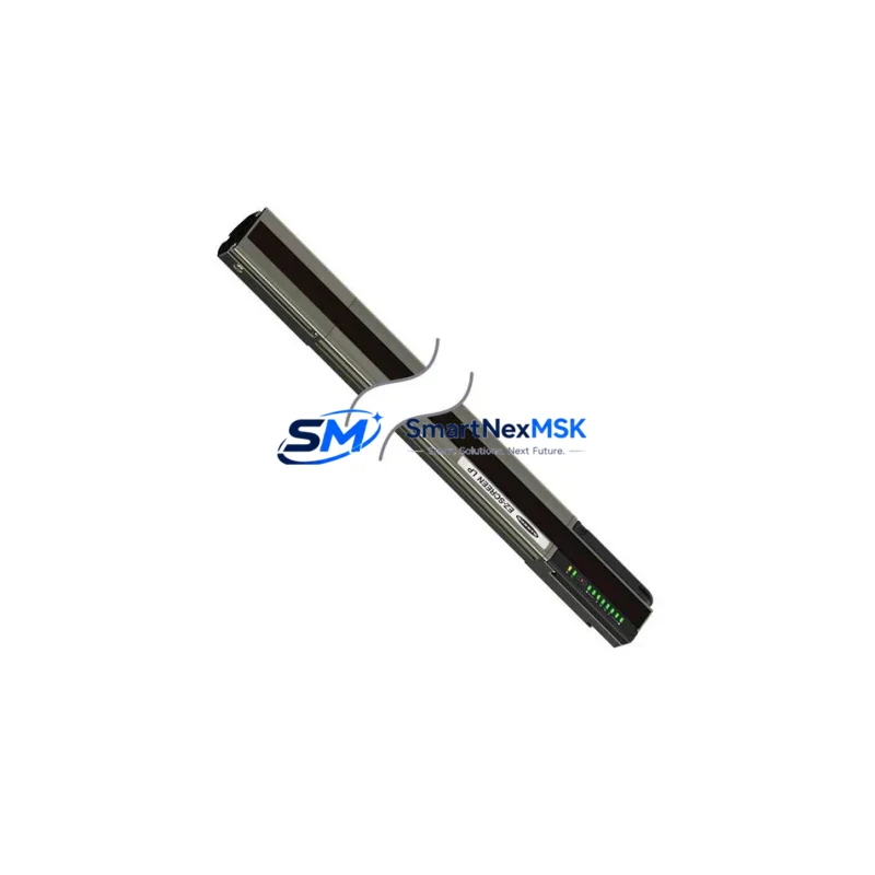
Banner IVUTGPR04 Maintenance-Ready Spare for iVu Series Automation
The Banner IVUTGPR04 is an original iVu Series image-based sensor designed for industrial vision inspection, presence/absence detection, and pattern matching in automated production lines. Also referenced under part numbers TSBC-ACRTC, 881-620160, 281-501049-C, and 208-501049-7, this unit integrates a CMOS imager, onboard processor, and a color touchscreen display into a single compact housing — eliminating the need for a separate controller or PC. For maintenance engineers managing aging iVu Series deployments, holding a verified replacement unit in stock is the most reliable strategy to minimize unplanned downtime and protect production continuity.
At SMARTNEXMSK, every IVUTGPR04 unit is sourced from authorized supply channels, subjected to pre-shipment functional testing, and backed by a 12-month warranty. We support long-term supply for discontinued and hard-to-source Banner components, making us a dependable partner for both planned maintenance cycles and emergency replacement scenarios.
Spare Maintenance Table
| Parameter | Specification / Value |
|---|---|
| Part Number | IVUTGPR04 |
| Cross-Reference SKUs | TSBC-ACRTC / 881-620160 / 281-501049-C / 208-501049-7 |
| Brand | Banner Engineering |
| Series | iVu Series (Image-Based Sensor) |
| Sensor Type | CMOS Vision Sensor with Integrated Touchscreen Display |
| Inspection Modes | Presence/Absence, Pattern Match, Bead, Area, Match, Sort |
| Communication Interface | RS-232, Discrete I/O, EtherNet/IP (model-dependent) |
| Supply Voltage | 10–30 V DC |
| Operating Temperature | 0 °C to +50 °C |
| Protection Rating | IP67 |
| Mounting | Standard M4 / bracket mount; drop-in compatible with existing iVu Series fixtures |
| Display | Integrated color touchscreen (2.4″ TFT) |
| Origin | USA |
| Compatibility | Direct replacement for iVu Series TG, BCR, and Color sensor families |
| Maintenance Recommendation | Inspect lens, clean sensor window, verify teach settings after installation |
| Warranty | 12 Months — covers functional defects under normal operating conditions |
| Pre-Shipment Testing | Yes — power-on, I/O signal, and communication verification |
| Lead Time | In-stock units ship within 1–3 business days |
Maintenance Planning for Continuous Operation
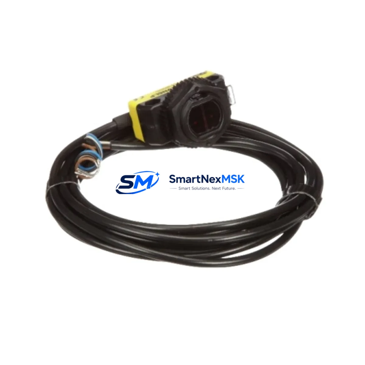
When a Banner IVUTGPR04 fails or degrades in a production environment, the fault rarely exists in isolation. A thorough maintenance response requires inspecting the entire sensor circuit and associated control infrastructure. Maintenance engineers should begin by verifying the 24 V DC power supply feeding the sensor — voltage sag or ripple is a common root cause of intermittent iVu Series faults that are misdiagnosed as sensor failure. Check the Banner iVu Series power cable assembly (typically a 5-pin M12 connector) for pin corrosion, insulation damage, or loose terminations at the junction box or terminal block.
On the I/O side, inspect the discrete output wiring to the PLC input card. If the system uses a Banner SC10 Series remote display or a Banner iVu Series remote teach input, verify that these auxiliary connections are intact and that the teach logic has not been corrupted by a power interruption. For systems integrated via EtherNet/IP, confirm that the managed switch port, IP address assignment, and EDS file configuration remain consistent with the replacement unit’s firmware version.
In control cabinets housing iVu Series sensors alongside other Banner devices — such as the Banner DX80 wireless I/O node or Banner K50 series indicator lights — inspect the shared terminal strips and fuse holders for signs of thermal stress or loose connections. If the IVUTGPR04 is part of a multi-sensor inspection station, also verify the status of adjacent Banner Q4X laser displacement sensors or Banner R58E retroreflective sensors that share the same PLC I/O module, as a single wiring fault can affect multiple channels simultaneously.
For facilities running older iVu Series installations, it is advisable to maintain a minimum spare inventory that includes: one IVUTGPR04 sensor unit, one spare M12 power/I/O cable set, one replacement lens cover or protective window, and a backup copy of the sensor’s inspection job file exported via the iVu Series PC software. This spare kit approach ensures that a complete sensor swap — including reconfiguration — can be completed within a single maintenance window, keeping unplanned downtime under two hours even in the most time-critical production environments.
Site Replacement Workflow
Step 1 — Isolate and document: Before removing the failed IVUTGPR04, photograph the existing wiring, note the sensor’s IP address (if networked), and export the current inspection job file from the iVu Series interface. This documentation eliminates reconfiguration guesswork during reinstallation.
Step 2 — Power down safely: De-energize the sensor circuit at the cabinet disconnect. Verify zero voltage at the M12 connector before disconnecting. Do not hot-swap iVu Series sensors — the integrated processor requires a clean power cycle to initialize correctly.
Step 3 — Mechanical swap: The IVUTGPR04 uses the same mounting footprint as other iVu Series TG models. Remove the existing bracket hardware, install the replacement unit, and torque mounting screws to the manufacturer’s specification. Verify that the lens-to-target distance matches the original setup using the integrated display’s live image view.
Step 4 — Restore configuration: Import the previously exported inspection job file via USB or the iVu Series PC software. If no backup exists, re-teach the sensor using the original reference part. Confirm that all pass/fail thresholds, output logic, and communication parameters match the production requirement before re-enabling the line.
Step 5 — Verify and document: Run a minimum of 20 test cycles with known-good and known-bad reference parts. Log the results and update the maintenance record with the replacement date, new unit serial number, and firmware version. This record supports warranty claims and future troubleshooting.
This workflow is compatible with direct replacement of legacy iVu Series units including earlier TSBC-ACRTC and 881-620160 variants, ensuring backward compatibility without requiring PLC program changes or mechanical modifications to existing fixtures.
Spare Parts Support FAQ
Q1: Is the IVUTGPR04 still available as a new original spare, or only as a refurbished unit?
All IVUTGPR04 units supplied by SMARTNEXMSK are sourced as original Banner Engineering components. Each unit undergoes pre-shipment power-on and I/O verification testing. A 12-month warranty is included with every shipment, covering functional defects under normal industrial operating conditions. Refurbished or remanufactured units are clearly identified as such — if not stated, the unit is original.
Q2: How do I confirm compatibility between the IVUTGPR04 and my existing iVu Series installation?
The IVUTGPR04 is a direct mechanical and electrical replacement for iVu Series TG sensor models sharing the same housing format. Cross-reference your existing part number against the listed SKUs: TSBC-ACRTC, 881-620160, 281-501049-C, and 208-501049-7. If your existing unit carries any of these numbers, the IVUTGPR04 is a confirmed drop-in replacement. For EtherNet/IP installations, verify that the firmware version of the replacement unit is compatible with your EDS file and PLC configuration before deployment.
Q3: What is the recommended spare inventory strategy for facilities running multiple iVu Series inspection stations?
For facilities with three or more iVu Series stations, we recommend maintaining at least one IVUTGPR04 unit on-site as a hot spare. Pair this with a pre-configured USB backup of each station’s inspection job file. This combination allows a complete sensor swap and reconfiguration in under two hours, meeting most production recovery SLAs. For critical 24/7 lines, consider a two-unit buffer to cover simultaneous failures during peak production periods.
Q4: What does the 12-month warranty cover, and how is a warranty claim processed?
The 12-month warranty covers all functional defects arising under normal operating conditions — including sensor processor failure, display malfunction, I/O output failure, and communication interface faults. Physical damage caused by incorrect installation, overvoltage, or environmental exposure beyond IP67 rating is excluded. To initiate a warranty claim, contact SMARTNEXMSK at sales@smartnexmsk.com or +86 18259474341 with your order number, unit serial number, and a description of the fault. Replacement or repair is typically processed within 5–7 business days of fault confirmation.
© 2026 SMARTNEXMSK. All rights reserved.
Original Source: https://smartnexmsk.com
Contact: sales@smartnexmsk.com | +86 18259474341