Bently Nevada 106765-16 Retrofit-Ready Interconnect Cable for 3500 Series Control Systems
The Bently Nevada 106765-16 is a precision-engineered interconnect cable designed for seamless integration within the Bently Nevada 3500 Series machinery protection and condition monitoring platform. As legacy control infrastructure ages and OEM support windows close, the 106765-16 serves as a critical retrofit component enabling engineers to restore, upgrade, and extend the operational life of existing 3500 rack-based monitoring systems without requiring a full platform migration.
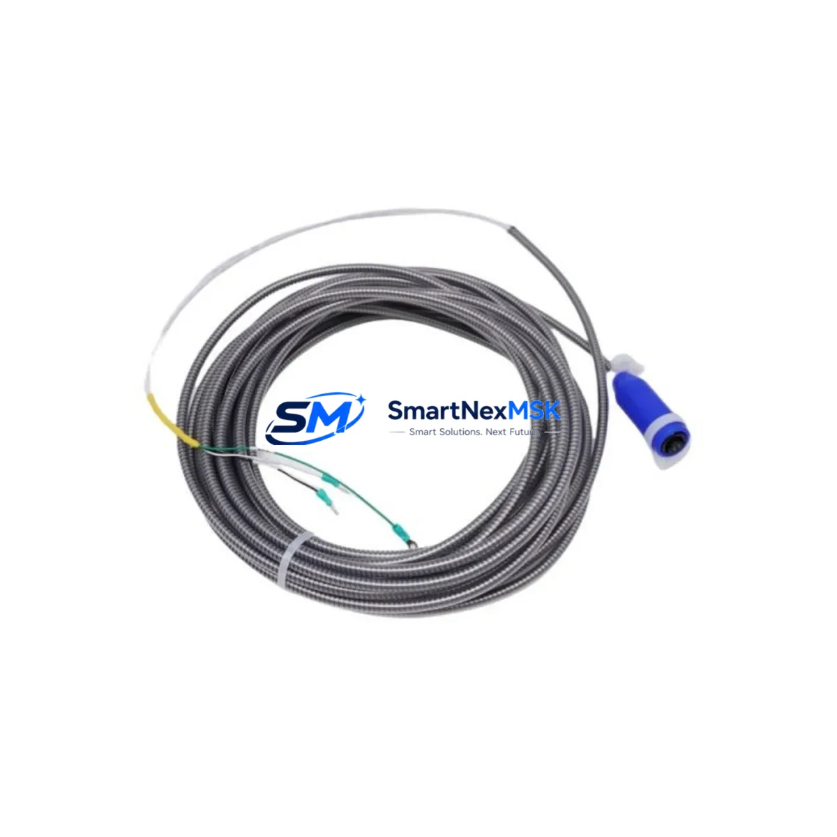
This cable provides the physical and electrical interface between the 3500/22M Transient Data Interface module, the 3500/42M Proximitor/Seismic Monitor, and associated field-mounted transducers including proximity probes, velocity sensors, and accelerometers. Its shielded construction and impedance-matched termination ensure signal integrity across long cable runs in electrically noisy industrial environments such as turbine halls, compressor stations, and rotating machinery skids.
Upgrade Compatibility Table
| Parameter | Details |
|---|---|
| Compatible Platform | Bently Nevada 3500 Series Machinery Protection System |
| Replaces / Supersedes | Earlier 106765-xx cable variants; field-wired custom assemblies |
| Connector Interface | Multi-pin shielded connector, rack-side and transducer-side terminations |
| Signal Compatibility | Proximitor (eddy-current), velocity, and accelerometer transducer signals |
| Communication Protocol | Analog signal transmission; compatible with 3500 System 1 software integration |
| Installation Requirement | No rack modification required; direct plug-in replacement |
| Retrofit Recommendation | Verify cable routing clearance and transducer gap voltage before energizing |
| Commissioning Note | Confirm module address and channel assignment in 3500 Rack Configuration Software |
| Warranty | 12 Months from date of shipment |
Retrofit Planning for Existing Automation Systems
When planning a retrofit of an aging Bently Nevada 3500 rack, the 106765-16 interconnect cable is typically one of the first components to be evaluated for replacement. Over years of continuous operation, cable insulation degrades, shield continuity is compromised, and connector contacts oxidize — all of which introduce noise floors that mask genuine machinery fault signatures. Replacing the 106765-16 as part of a planned outage restores the measurement baseline before any module-level diagnostics are performed.
A complete retrofit scope for a 3500 Series rack commonly involves the 3500/05 Power Supply Module, which must be verified for adequate current capacity when additional I/O modules such as the 3500/40M Proximitor Monitor or 3500/50 Tachometer Module are added to the rack. The 3500/20 Rack Interface Module governs communication between the rack and the host DCS or historian, and its firmware version must be confirmed compatible with the System 1 Evolution software version in use at the site.
For sites migrating from older Bently Nevada 7200 Series or 3300 Series monitors, the 106765-16 cable assembly supports the transducer field wiring reuse strategy, allowing existing Bently Nevada 330130 proximity probe cables and 330180 extension cables to remain in place while the rack-side termination is updated. This significantly reduces field labor hours and eliminates the need to re-route cables through conduit or cable trays.
Terminal block wiring must be carefully mapped during the retrofit. The 3500 rack uses a dedicated I/O terminal strip for each monitor module, and the pinout of the 106765-16 must be cross-referenced against the original field wiring diagram. Where drawings are unavailable, the Bently Nevada 3500 Field Wiring Diagram tool or the module’s internal label can be used to reconstruct the termination schedule. Power supply polarity, shield drain wire routing, and barrier ground connections should all be verified before the cable is energized.
Sites operating Bently Nevada systems alongside Emerson DeltaV DCS or Ovation control platforms should confirm that the 3500/20 Rack Interface Module’s Modbus TCP or OPC DA/UA configuration is preserved during the cable swap. Any interruption to the communication link between the 3500 rack and the DCS historian will generate alarm floods that must be suppressed in the DCS faceplate before maintenance begins. The 3500 Rack Configuration Software should be used to export the current rack configuration file as a backup prior to any hardware change.
Downtime Control During System Migration
Minimizing unplanned downtime during a 3500 Series cable retrofit requires a structured pre-outage preparation protocol. Before the maintenance window opens, the existing rack configuration should be exported from the 3500 Rack Configuration Software and stored on a secure engineering workstation. All active alarm setpoints, transducer scale factors, and OK relay logic should be documented so they can be verified after the new 106765-16 cable is installed.
During the cable swap, the associated monitor module — typically the 3500/42M or 3500/40M — should be placed in Bypass mode using the front-panel keyswitch or via the software interface. This prevents spurious trip signals from propagating to the machinery protection relay outputs while the transducer circuit is open. Once the 106765-16 is seated and the connector locking mechanism is engaged, the transducer gap voltage should be measured at the monitor module’s test points to confirm the proximity probe is within its linear range before Bypass mode is released.
For critical rotating machinery where even brief monitoring gaps are unacceptable, a temporary portable vibration analyzer such as the Bently Nevada SCOUT 100 or an equivalent handheld instrument can be connected directly to the transducer field wiring to maintain continuous vibration surveillance during the cable replacement. This approach preserves the original program logic in the 3500 rack while the interconnect is being serviced, ensuring that the control room HMI continues to display live machinery data without interruption.
After the retrofit is complete, a full channel functional test should be performed: verify OK status on all channels, confirm alarm and danger setpoints are active, and check that the System 1 trend data resumes without gaps. The 12-month warranty on the 106765-16 covers manufacturing defects and connector integrity, providing assurance for the post-retrofit commissioning period.
Retrofit Support FAQ
Q: Is the 106765-16 a direct drop-in replacement for earlier Bently Nevada interconnect cable variants?
A: Yes. The 106765-16 is designed as a direct replacement for earlier -xx suffix variants in the same cable family. Connector geometry and pinout are preserved. Verify the cable length suffix matches your rack-to-transducer distance before ordering.
Q: What commissioning steps are required after installing the 106765-16?
A: After installation, measure transducer gap voltage at the monitor module test points, confirm OK relay status, verify alarm setpoints in the 3500 Rack Configuration Software, and check System 1 data continuity. Release Bypass mode only after all channels show normal status.
Q: Can the 106765-16 be used with non-Bently Nevada transducers?
A: The cable is optimized for Bently Nevada proximity probes and extension cables. Use with third-party transducers requires verification of signal range, bias voltage, and sensitivity against the 3500 monitor module’s input specifications. Consult the module datasheet before proceeding.
Q: What does the 12-month warranty cover?
A: The warranty covers manufacturing defects in materials and workmanship, including connector integrity and cable shielding continuity. It does not cover damage resulting from incorrect installation, over-voltage, or mechanical abuse. Warranty claims are processed within 5 business days of receipt of the returned unit.
© 2026 SMARTNEXMSK. All rights reserved.
Original Source: https://smartnexmsk.com
Contact: sales@smartnexmsk.com | +86 18259474341


