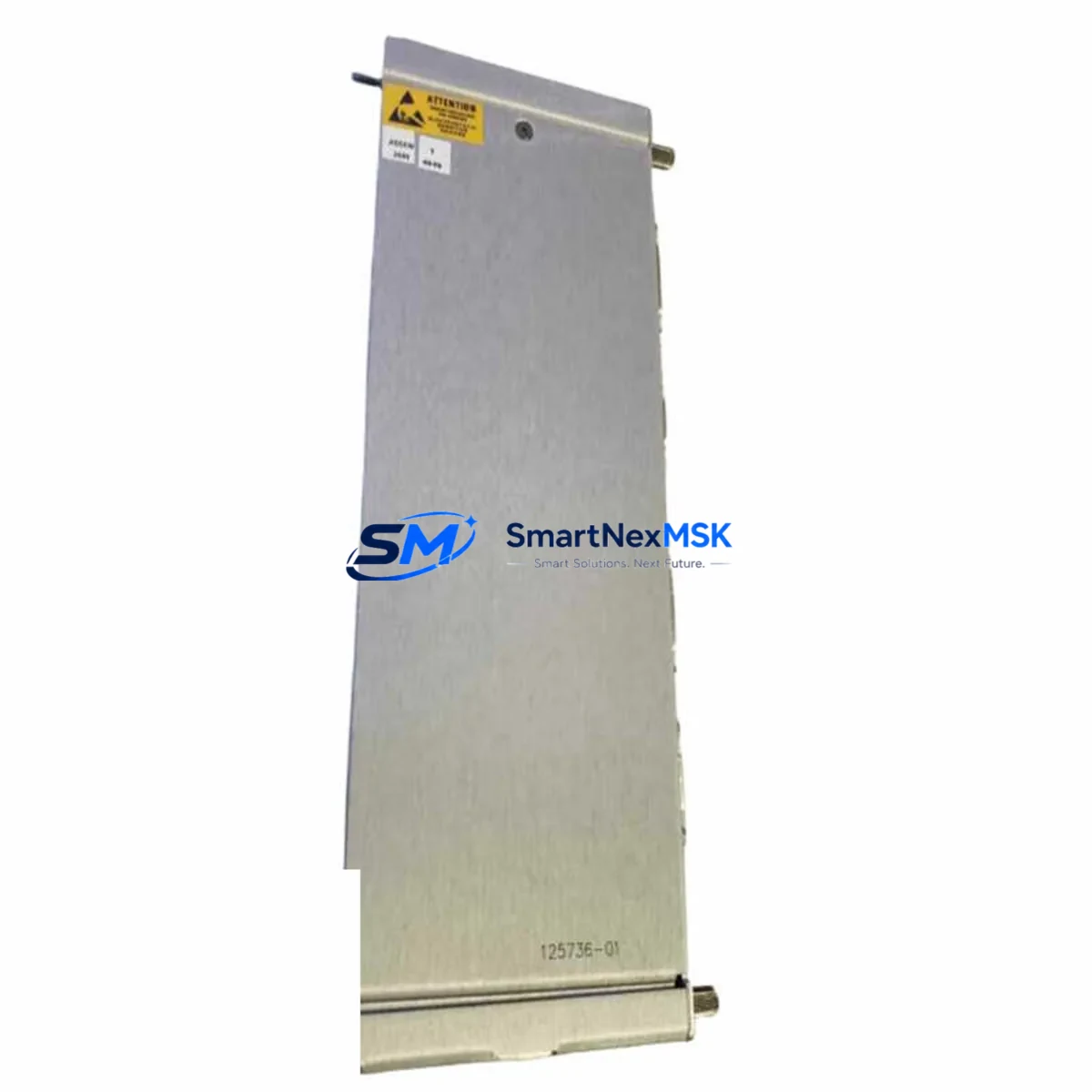
Bently Nevada 125736-01 Retrofit-Ready Communication Gateway for 3500 Series Control Systems
The Bently Nevada 125736-01 is a retrofit-ready Communication Gateway Module engineered for seamless integration into existing 3500 Series machinery protection and condition monitoring systems. As legacy 3500 Series installations age and original gateway modules reach end-of-life, the 125736-01 provides a verified drop-in replacement path that preserves existing wiring infrastructure, rack architecture, and communication topology — minimizing engineering rework and unplanned downtime during system modernization.
Industrial facilities operating continuous-process equipment — including turbines, compressors, pumps, and generators — rely on the 3500 Series platform for real-time vibration monitoring and trip protection. When the original communication gateway fails or becomes obsolete, the entire data acquisition chain between field sensors, the 3500/20 Rack Interface Module, and the plant DCS or historian is interrupted. The 125736-01 restores this chain with full backward compatibility across Modbus RTU, Modbus TCP/IP, and proprietary Bently Nevada communication protocols, ensuring that upstream SCADA systems and System 1 Evolution software continue to receive uninterrupted process data.
Before committing to a retrofit, engineers should verify several critical parameters. First, confirm that the host rack — typically a 3500/05 Rack Power Supply-equipped 19-inch chassis — provides sufficient backplane power budget for the 125736-01 alongside co-installed modules such as the 3500/40M Proximitor/Seismic Monitor, 3500/42M Proximitor/Seismic Monitor, and 3500/50 Tachometer Module. Second, review terminal block wiring assignments: the 125736-01 uses the same I/O connector pinout as its predecessor, but technicians should cross-reference the field wiring diagram against the module’s terminal identification label before energizing. Third, validate the backplane slot address — the gateway must occupy the designated communication slot defined in the rack configuration, as the 3500/15 Rack Interface Module assigns slot-based addressing that the host controller references during polling cycles.
Program compatibility is a frequent concern during gateway replacement. The 125736-01 retains the same register map structure used by earlier 3500 Series communication modules, meaning that existing Modbus polling tables configured in the plant DCS — whether a Honeywell Experion PKS, Emerson DeltaV, or third-party SCADA — do not require modification. However, if the site has migrated to Ethernet-based communication using the 3500/92 Communication Gateway as an intermediate node, the network IP addressing and subnet configuration must be updated in the replacement module before commissioning. This step is performed using the Bently Nevada Rack Configuration Software (RCS) connected via the front-panel RS-232 programming port or USB adapter cable.
HMI screen validation is another mandatory step in the retrofit workflow. Operators should confirm that all dynamic data tags bound to the gateway’s Modbus registers — including overall vibration amplitude, gap voltage, rotational speed, and alarm status bits — continue to resolve correctly after the module swap. Any tag that references a hardware-specific register offset must be re-verified against the 125736-01 register map documentation. Sites running Wonderware InTouch, iFIX, or Ignition SCADA should perform a full tag scan and alarm acknowledgment test before returning the machine train to service.
Communication link integrity testing should be completed before final sign-off. This includes verifying Modbus response times, checking for CRC error counts over a 30-minute observation window, and confirming that the 3500/22M Transient Data Interface — if installed in the same rack — continues to synchronize transient capture events through the gateway without packet loss. Where Ethernet connectivity is used, a network loop test between the gateway and the plant historian confirms end-to-end data path integrity.
All 125736-01 units supplied by SMARTNEXMSK are sourced from verified industrial supply channels, functionally tested prior to shipment, and covered by a 12-month warranty against manufacturing defects and operational failure. Units are shipped from Xiamen with full ESD packaging, and each module is accompanied by a test report confirming communication handshake verification and register map validation.
Upgrade Compatibility Table
| Parameter | Details |
|---|---|
| Compatible Platform | Bently Nevada 3500 Series Machinery Protection System |
| Slot Requirement | Designated communication slot in 3500/05 or compatible rack |
| Communication Protocols | Modbus RTU, Modbus TCP/IP, Bently Nevada proprietary protocol |
| Backplane Interface | 3500 Series standard backplane connector — direct replacement |
| Terminal Wiring | Same pinout as predecessor; verify field wiring before energizing |
| IP Configuration | Required for Ethernet variants; configure via RCS software |
| Register Map | Backward-compatible with existing DCS/SCADA Modbus polling tables |
| Replacement Recommendation | Direct drop-in for end-of-life 3500 Series communication gateways |
| Commissioning Tool | Bently Nevada Rack Configuration Software (RCS) via RS-232/USB |
| Warranty | 12 months — covers manufacturing defects and operational failure |
Retrofit Planning for Existing Automation Systems
A successful 125736-01 retrofit begins with a complete rack audit. Identify all modules currently installed in the 3500 Series chassis: document the 3500/05 Rack Power Supply output capacity, list all monitor modules by slot position, and record the firmware revision of the 3500/15 Rack Interface Module. This audit establishes the baseline against which the replacement gateway’s power draw and slot assignment are validated.
For sites where the original gateway also served as the primary interface between the 3500 rack and a 3500/92 Communication Gateway acting as a protocol bridge to a Profibus DP or FOUNDATION Fieldbus segment, the retrofit plan must account for the protocol translation layer. In these configurations, the 125736-01 handles the Modbus side of the bridge, while the 3500/92 manages the fieldbus segment — both modules must be re-commissioned together to restore full communication continuity.
I/O expansion considerations are also relevant when the retrofit coincides with a broader system upgrade. If the site is adding new measurement points — for example, integrating additional proximity probes via a 3500/40M Proximitor/Seismic Monitor or expanding tachometer inputs through a 3500/50 Tachometer Module — the gateway’s polling configuration must be updated to include the new register addresses assigned to the expanded I/O. This update is performed in the RCS software before the rack is returned to service.
Control cabinet layout should also be reviewed during retrofit planning. The 125736-01 occupies a standard 3500 Series module footprint and does not require additional DIN rail space or external power conditioning. However, if the cabinet also houses a separate Bently Nevada 3300 Series monitor or a standalone TDXnet Data Acquisition Module, the communication wiring between these systems and the 3500 rack must be re-verified after the gateway swap to confirm that inter-system polling is unaffected.
Downtime Control During System Migration
Minimizing production downtime during a gateway replacement requires a structured hot-swap protocol. Where the process permits a brief controlled shutdown, the recommended sequence is: (1) place the DCS in manual control mode to freeze setpoints and prevent spurious trips during the module swap; (2) document all current alarm setpoints and trip thresholds displayed on the System 1 Evolution operator interface; (3) remove the failed gateway module and install the 125736-01 in the same backplane slot; (4) apply power and confirm that the module’s status LED sequence matches the expected initialization pattern; (5) use RCS to verify the communication configuration and, if Ethernet is used, assign the correct IP address; (6) restore DCS to automatic control and confirm that all vibration, gap, and speed channels are reporting correctly.
For continuous-process facilities where even a brief shutdown is unacceptable, a parallel commissioning approach is recommended: install and configure the 125736-01 in a bench test environment using a spare rack or a 3500/05 Rack Power Supply test chassis, validate all register map responses against the live system’s expected values, and then execute the physical swap during the next scheduled maintenance window. This approach reduces the in-situ commissioning time to under 30 minutes and preserves the original program logic and HMI tag bindings without modification.
Throughout the migration, maintain a written record of all configuration changes, IP address assignments, and alarm setpoint verifications. This documentation supports post-retrofit audits and provides a reference baseline for future maintenance cycles.
Retrofit Support FAQ
Q1: Is the 125736-01 a direct replacement for all communication gateway variants in the 3500 Series?
The 125736-01 is compatible with the standard 3500 Series communication slot and supports Modbus RTU and Modbus TCP/IP protocols. Sites using specialized protocol variants — such as Profibus DP or FOUNDATION Fieldbus — should confirm the specific communication option code of their original module before ordering. SMARTNEXMSK’s technical team can assist with compatibility verification based on the original module’s part number suffix.
Q2: What wiring changes are required during installation?
In most cases, no wiring changes are required. The 125736-01 uses the same terminal block pinout as its predecessor. Technicians should visually verify field wiring labels against the module’s terminal identification before energizing, and confirm that cable shield grounding is intact at the rack chassis ground point.
Q3: How is the module configured after installation?
Configuration is performed using Bently Nevada Rack Configuration Software (RCS) connected to the module’s front-panel RS-232 port or via a USB adapter cable. The RCS session allows the technician to set the Modbus node address, baud rate, parity, and — for Ethernet variants — the IP address and subnet mask. Configuration typically takes 15–30 minutes for an experienced technician.
Q4: What does the 12-month warranty cover?
All 125736-01 units supplied by SMARTNEXMSK carry a 12-month warranty covering manufacturing defects and operational failure under normal industrial operating conditions. Each unit is functionally tested and communication-verified prior to shipment. Warranty claims are processed directly through SMARTNEXMSK’s after-sales team, with replacement units dispatched within 3 business days of confirmed fault diagnosis.
© 2026 SMARTNEXMSK. All rights reserved.
Original Source: https://smartnexmsk.com
Contact: sales@smartnexmsk.com | +86 18259474341


