Bently Nevada 125840-01 Maintenance Spare 3500 Series: Spare Replacement & Industrial Downtime Risk Control
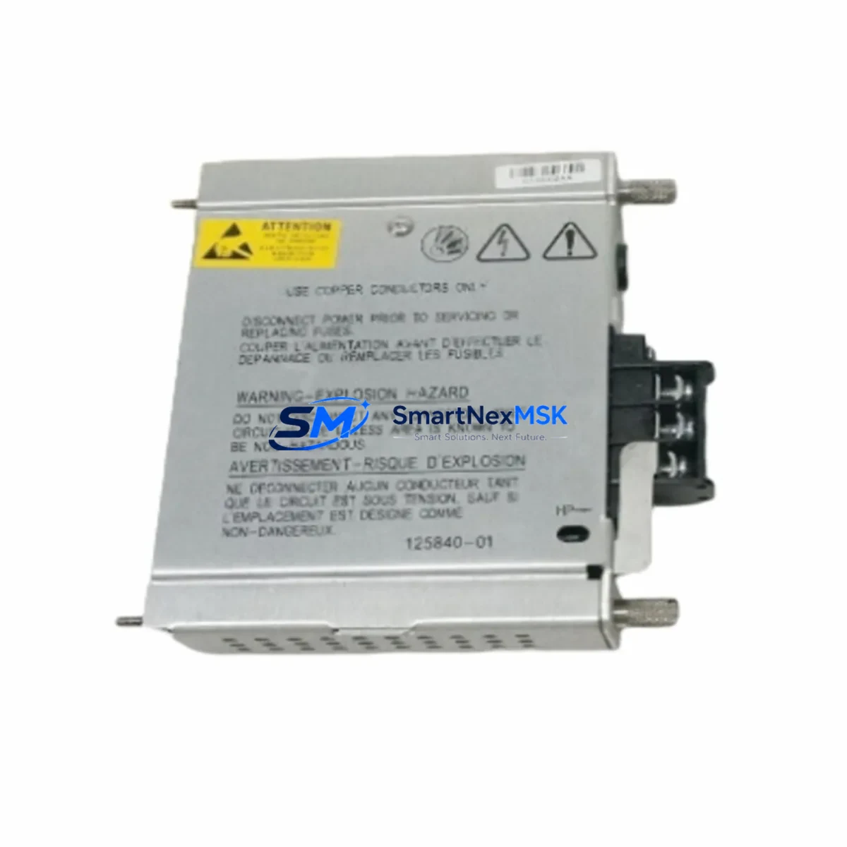
The Bently Nevada 125840-01 is an original AC power supply module engineered for the 3500 Series machinery protection and condition monitoring rack system. As a critical power backbone for the entire 3500 rack assembly, this module supplies regulated DC power to all installed monitor cards, including vibration monitors, temperature monitors, and relay output modules. When this power supply degrades or fails, the entire rack loses its protective function — leaving rotating machinery unprotected and exposing the facility to unplanned downtime, equipment damage, and safety risk.
For maintenance engineers managing turbines, compressors, pumps, and other critical rotating assets, maintaining a verified spare of the 125840-01 in the local parts inventory is a fundamental element of any reliability-centered maintenance (RCM) strategy. This module is not a commodity item — it is a precision-regulated power source that must meet Bently Nevada’s original electrical specifications to ensure the 3500 rack operates within its certified monitoring parameters.
SMARTNEXMSK supplies the 125840-01 as a tested, original spare with full functional verification prior to shipment. Each unit is inspected for output voltage stability, inrush current behavior, and thermal performance. A 12-month warranty is included with every shipment, covering manufacturing defects and functional failures under normal operating conditions.
Spare Maintenance Table
| Parameter | Specification / Detail |
|---|---|
| Part Number / SKU | 125840-01 |
| Brand | Bently Nevada |
| Series | 3500 Series Machinery Protection System |
| Module Type | AC Power Supply Module |
| Input Voltage | 85–264 VAC, 47–63 Hz (universal AC input) |
| Output | Regulated DC power for 3500 rack backplane |
| Rack Compatibility | 3500/15 Rack, 3500/20 Rack, 3500/22M Rack |
| Form Factor | Single-slot rack-mount module |
| Operating Temperature | 0°C to 65°C (32°F to 149°F) |
| Application Environment | Industrial plant floor, control room, machinery skid |
| Origin | United States |
| Condition | Original / Genuine Spare |
| Pre-shipment Testing | Functional output verification, voltage stability check |
| Warranty | 12 Months from shipment date |
| Lead Time | In stock — ships within 1–3 business days |
| Maintenance Recommendation | Replace at first sign of output instability or rack alarm; keep one spare on-site |
Maintenance Planning for Continuous Operation
When a 125840-01 power supply is flagged during a control cabinet inspection or triggers a rack power fault alarm, the replacement procedure should be treated as a system-level event — not an isolated module swap. Maintenance engineers should use this opportunity to perform a comprehensive audit of the entire 3500 rack and its associated electrical infrastructure.
Begin by verifying the AC input feed to the rack. The 125840-01 draws power from the facility’s instrument power distribution panel; any upstream voltage sag, harmonic distortion, or loose terminal connection at the power entry point can accelerate power supply wear. Check the terminal block connections and the dedicated circuit breaker or fuse protecting the rack’s AC feed.
Within the rack itself, inspect the 3500/15 or 3500/20 rack backplane for signs of connector oxidation or mechanical damage at the power supply slot. A degraded backplane connector can cause intermittent power faults even after a new 125840-01 is installed. If the facility operates a redundant power configuration, the companion 125840-01 redundant power supply module (installed in the adjacent slot) should be tested simultaneously — a single-point failure in one supply often indicates aging in both units if they were installed at the same time.
Review the monitor cards drawing power from the rack. The 3500/40M proximitor/seismic monitor, 3500/42M proximitor/seismic monitor, and 3500/45 position monitor are common occupants of the same rack and should be checked for any latent alarms or calibration drift that may have been masked during the power fault event. Similarly, the 3500/32 4-channel relay module and 3500/33 16-channel relay module should be tested to confirm that relay outputs are responding correctly after power is restored.
For facilities using the 3500/92 communication gateway module or 3500/93 communication gateway for Modbus or OPC integration with the plant DCS or SCADA system, verify that the communication link re-establishes cleanly after the power supply replacement. A power interruption can sometimes cause the gateway to lose its configuration or require a soft reset.
If the 3500 rack is installed in a control cabinet alongside other instrumentation — such as signal isolators, loop-powered transmitters, or safety relay modules — inspect the cabinet’s internal wiring harness for any heat damage or insulation degradation near the power supply bay. Overheating from a failing 125840-01 can affect adjacent wiring and terminal strips.
For long-term asset life extension, consider scheduling the 125840-01 replacement as part of a planned 5-year overhaul cycle for the entire 3500 rack system, coordinated with the replacement of aging monitor cards and the recalibration of all connected proximity probes and accelerometers.
Site Replacement Workflow
Step 1 — Pre-replacement verification: Confirm the replacement 125840-01 part number matches the installed unit. Check the label on the existing module for revision suffix (e.g., -01) and verify compatibility with your specific rack model (3500/15, 3500/20, or 3500/22M). The 125840-01 is backward-compatible across the 3500 Series rack family.
Step 2 — Safe isolation: Coordinate with the control room operator to acknowledge and suppress rack alarms before beginning the swap. If the rack is in a non-redundant power configuration, the machinery protection function will be temporarily suspended during the replacement. Follow site-specific LOTO (Lockout/Tagout) procedures for the AC input circuit.
Step 3 — Module extraction: The 125840-01 is a hot-swap-capable module in redundant configurations. In non-redundant installations, de-energize the AC input before extraction. Use the front-panel ejector levers to disengage the module from the backplane connector. Avoid applying lateral force to the module during extraction.
Step 4 — Installation and power-up: Seat the replacement 125840-01 firmly into the rack slot until the ejector levers click into the locked position. Restore AC power and observe the module’s front-panel LED indicators. A solid green PWR LED confirms normal operation. Monitor the rack’s system status display for any residual alarms.
Step 5 — Post-replacement functional check: Verify that all monitor cards in the rack are displaying live process values and that no new alarms have been generated. Confirm that the communication gateway (if installed) has re-established its data link. Document the replacement in the site maintenance log with the new module’s serial number and installation date.
This workflow minimizes total downtime to under 30 minutes for a prepared maintenance team with a verified spare on hand — reinforcing why on-site inventory of the 125840-01 is a best practice for any facility operating Bently Nevada 3500 Series protection systems.
Spare Parts Support FAQ
Q1: Is the 125840-01 compatible with all 3500 Series rack models?
Yes. The 125840-01 AC power supply module is designed for use across the Bently Nevada 3500 Series rack family, including the 3500/15, 3500/20, and 3500/22M rack configurations. It is the standard single-slot AC power supply for this platform. Always verify the rack model and power supply slot designation before ordering to confirm fit.
Q2: What pre-shipment testing does SMARTNEXMSK perform on the 125840-01?
Every 125840-01 unit shipped by SMARTNEXMSK undergoes functional output verification, including DC output voltage stability testing and inrush current behavior assessment. Units that do not meet original Bently Nevada electrical specifications are rejected. A test report is available upon request. All units are shipped with a 12-month warranty covering manufacturing defects and functional failures under normal operating conditions.
Q3: How should I manage 125840-01 inventory for a multi-rack installation?
For facilities operating two or more 3500 Series racks, the recommended minimum spare holding is one 125840-01 per every two racks, stored in a climate-controlled parts room. For critical assets (gas turbines, large compressors) where unplanned downtime carries high financial or safety risk, a dedicated spare per rack is advisable. SMARTNEXMSK supports long-term supply agreements and can reserve stock for scheduled maintenance windows.
Q4: Can the 125840-01 replace older or discontinued Bently Nevada power supply variants?
The 125840-01 is the current production part number for the 3500 Series AC power supply. It is designed to replace earlier power supply variants used in legacy 3500 rack installations. Compatibility should be confirmed against the rack’s original bill of materials or the Bently Nevada 3500 Series system documentation. SMARTNEXMSK’s technical team can assist with cross-reference verification prior to order placement.
© 2026 SMARTNEXMSK. All rights reserved.
Original Source: https://smartnexmsk.com
Contact: sales@smartnexmsk.com | +86 18259474341


