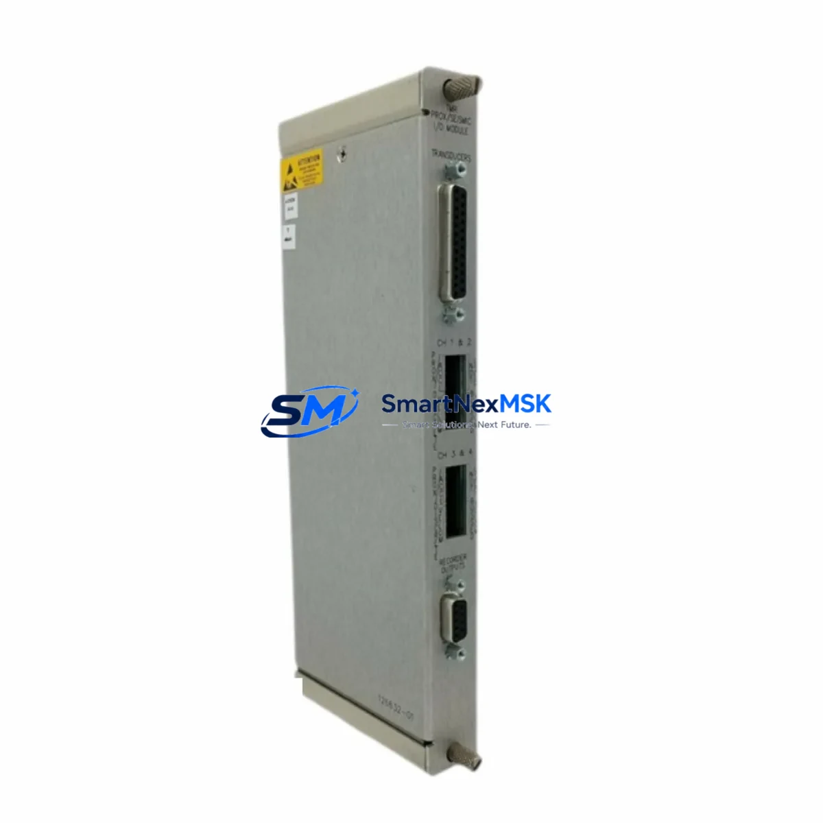
Bently Nevada 126632-01 Maintenance-Ready Spare for 3500 Automation
The Bently Nevada 126632-01 is an original Triple Modular Redundancy (TMR) I/O module engineered for the 3500 Series machinery protection and vibration monitoring platform. In industrial facilities where continuous uptime is non-negotiable — refineries, compressor stations, turbine halls, and rotating equipment monitoring rooms — this module occupies a critical position in the control cabinet. A failed or degraded 126632-01 can interrupt vibration signal acquisition across multiple channels simultaneously, triggering unplanned shutdowns and costly production losses. Stocking a verified, tested spare is the single most effective measure a maintenance team can take to compress mean time to repair (MTTR) and protect asset availability.
Sourced directly from authorized supply chains and subjected to pre-shipment functional verification, each 126632-01 unit shipped by SMARTNEXMSK carries a 12-month warranty covering manufacturing defects and operational failures under normal service conditions. Every module is inspected for firmware revision compatibility, connector integrity, and channel isolation before dispatch, ensuring it arrives ready for immediate installation without additional bench testing.
Spare Maintenance Table
| Parameter | Specification / Detail |
|---|---|
| Part Number | 126632-01 |
| Brand | Bently Nevada |
| Series | 3500 Series Machinery Protection System |
| Module Type | TMR (Triple Modular Redundancy) I/O Module |
| Application | Vibration monitoring, machinery protection, rotating equipment |
| Compatibility | 3500/20, 3500/22M, 3500/25, 3500/32, 3500/40M, 3500/42M, 3500/44M, 3500/45, 3500/50, 3500/60, 3500/61, 3500/62, 3500/64, 3500/72M, 3500/77 racks and associated I/O slots |
| Input/Output | Multi-channel analog I/O for transducer signal conditioning |
| Operating Voltage | 24 VDC (rack-supplied) |
| Operating Temperature | 0°C to +60°C (32°F to 140°F) |
| Mounting | 3500 Series rack slot, DIN-compatible backplane |
| Weight | 460 g (approx.) |
| Origin | United States |
| Condition | Original, new or refurbished-to-spec, pre-shipment tested |
| Warranty | 12 months from date of shipment |
| Lead Time | In-stock: ships within 3–5 business days; ex-stock subject to availability |
| Maintenance Recommendation | Inspect connector pins and backplane contacts every 12 months; verify channel calibration annually; replace on first sign of signal drift or TMR voting discrepancy |
Maintenance Planning for Continuous Operation
When a 126632-01 TMR I/O module is flagged for replacement during a planned outage or emergency callout, experienced maintenance engineers treat the event as a trigger for a broader cabinet inspection. The 3500 Series rack is a tightly integrated system, and a single degraded module often signals stress on adjacent components that share the same power bus, backplane, or signal loop.
Begin with the 3500/15 Power Supply Module — the primary source of regulated 24 VDC to all rack slots. A power supply operating outside its voltage tolerance window will accelerate wear on every I/O module in the rack, including the 126632-01. Measure output voltage under load and compare against the rated specification before installing the replacement module. If ripple or sag is detected, schedule the 3500/15 for concurrent replacement.
Next, inspect the 3500/20 Rack Interface Module (RIM), which manages communication between the 3500 rack and the host DCS or SCADA system. A degraded RIM can cause intermittent data loss that mimics I/O module faults, leading to misdiagnosis. Verify Modbus or Ethernet/IP communication integrity using the System 1 software diagnostic suite before closing the work order.
The 3500/22M Transient Data Interface (TDI) and 3500/25 Enhanced Keyphasor Module are frequently co-located with the 126632-01 in vibration monitoring racks. The Keyphasor signal is the timing reference for phase and 1X/2X amplitude measurements; a worn or contaminated Keyphasor connector will corrupt readings across all channels that depend on it. Clean and re-torque all Keyphasor wiring terminals during the same maintenance window.
For facilities running eddy-current proximity probes, inspect the associated 3500/40M Proximitor I/O Module and its field wiring. Probe cable shield continuity and barrier ground integrity should be verified with a calibrated insulation resistance tester. Similarly, if the rack includes a 3500/42M Velocity/Acceleration Input Module, check accelerometer cable connectors for fretting corrosion — a common failure mode in high-vibration environments.
Do not overlook the 3500/32 4-Channel Relay Output Module. Relay contacts that have experienced repeated trip cycling may exhibit increased contact resistance, which can delay or prevent protective shutdown commands. Test each relay channel with a contact resistance meter and replace the module if any channel exceeds the manufacturer’s threshold.
Finally, review the 3500/92 Communication Gateway Module if the rack is integrated into a plant-wide historian or asset management system. Firmware version mismatches between the gateway and the replacement 126632-01 can cause configuration upload failures. Confirm firmware compatibility before energizing the rack, and retain a copy of the rack configuration file as a rollback baseline.
For facilities managing aging 3500 Series installations, maintaining a minimum spare inventory of one 126632-01, one 3500/15 power supply, and one 3500/20 RIM provides a practical buffer against the most common single-point failure scenarios without excessive capital commitment.
Site Replacement Workflow
Step 1 — Pre-work documentation: Download and archive the current rack configuration using System 1 software or the 3500 Rack Configuration Utility. Record all channel setpoints, alarm thresholds, and transducer scaling factors. This baseline is essential for post-replacement verification and serves as the rollback reference if the new module requires re-configuration.
Step 2 — Safe isolation: Coordinate with the control room to place the affected monitoring channels in bypass mode before removing the 126632-01. In TMR systems, bypassing a single channel allows the remaining two channels to maintain voting integrity and prevents spurious trips during the swap. Follow site-specific LOTO (Lockout/Tagout) procedures for the rack power supply.
Step 3 — Module extraction and inspection: Remove the 126632-01 by releasing the front-panel locking levers and sliding the module clear of the backplane connector. Inspect the backplane connector pins for bent contacts, oxidation, or debris. Clean with approved electronics contact cleaner and allow to dry completely before inserting the replacement module.
Step 4 — Replacement installation: Insert the new 126632-01 firmly until the backplane connector is fully seated and the locking levers engage. The module’s LED status indicators should illuminate in the expected sequence during self-test. A solid green System OK LED confirms successful initialization.
Step 5 — Configuration restore and verification: Upload the saved rack configuration to the replacement module. Verify all channel setpoints, full-scale ranges, and alarm thresholds match the archived baseline. Apply a known reference signal to each input channel and confirm the displayed value matches the expected engineering unit output within the module’s specified accuracy band.
Step 6 — Return to service: Remove the channel bypass, confirm normal voting status in the System 1 display, and document the replacement in the site maintenance management system (CMMS). Update the spare parts inventory record to trigger reorder of a replacement 126632-01 for the next event.
This workflow is equally applicable when upgrading from an earlier 126632-0x revision to the 126632-01, as the physical form factor and backplane pinout are backward-compatible across the 3500 Series rack family.
Spare Parts Support FAQ
Q1: What is the shelf life of a stored 126632-01, and how should it be stored?
When stored in its original anti-static packaging in a climate-controlled environment (15°C–25°C, relative humidity below 60%, away from direct sunlight and magnetic fields), the 126632-01 has an effective shelf life of 5–7 years. Electrolytic capacitors on the board may require a brief re-formation cycle if the module has been stored for more than 3 years before installation. SMARTNEXMSK recommends a pre-installation power-on test for any module stored beyond 24 months.
Q2: How do I verify compatibility between the 126632-01 and my existing 3500 rack revision?
Compatibility is determined by the rack chassis revision, backplane revision, and System 1 software version. The 126632-01 is compatible with all standard 3500 Series rack configurations. Provide your rack serial number and System 1 version to our technical team at sales@smartnexmsk.com, and we will confirm compatibility and advise on any firmware update requirements before shipment.
Q3: What pre-shipment testing does SMARTNEXMSK perform on the 126632-01?
Each unit undergoes a multi-point inspection covering: visual inspection of PCB, connectors, and housing; power-on self-test with LED status verification; channel input/output functional test using calibrated signal sources; insulation resistance check between signal commons and chassis ground; and firmware version verification. A test report is available upon request and accompanies units shipped under formal purchase orders.
Q4: What does the 12-month warranty cover, and what is the RMA process?
The 12-month warranty covers manufacturing defects, component failures, and functional non-conformance under normal operating conditions as defined in the Bently Nevada 3500 Series installation manual. It does not cover damage resulting from incorrect installation, overvoltage events, or physical impact. To initiate an RMA, contact sales@smartnexmsk.com with the original order number, a description of the observed fault, and the module serial number. SMARTNEXMSK will issue an RMA authorization within 2 business days and arrange return shipping coordination.
© 2026 SMARTNEXMSK. All rights reserved.
Original Source: https://smartnexmsk.com
Contact: sales@smartnexmsk.com | +86 18259474341


