Bently Nevada 133819-02 Spare for 3500 Series Automation
The Bently Nevada 133819-02 is an original RTD/TC Temperature I/O Module engineered for continuous deployment within Bently Nevada 3500 Series machinery protection and condition monitoring systems. For maintenance engineers managing rotating equipment protection infrastructure — turbines, compressors, pumps, and generators — this module represents a critical spare that directly governs temperature channel integrity across the entire protection rack. Unplanned downtime caused by a failed temperature I/O module can cascade into full machinery trip events, production loss, and costly emergency procurement. Stocking a verified 133819-02 spare eliminates that risk entirely.
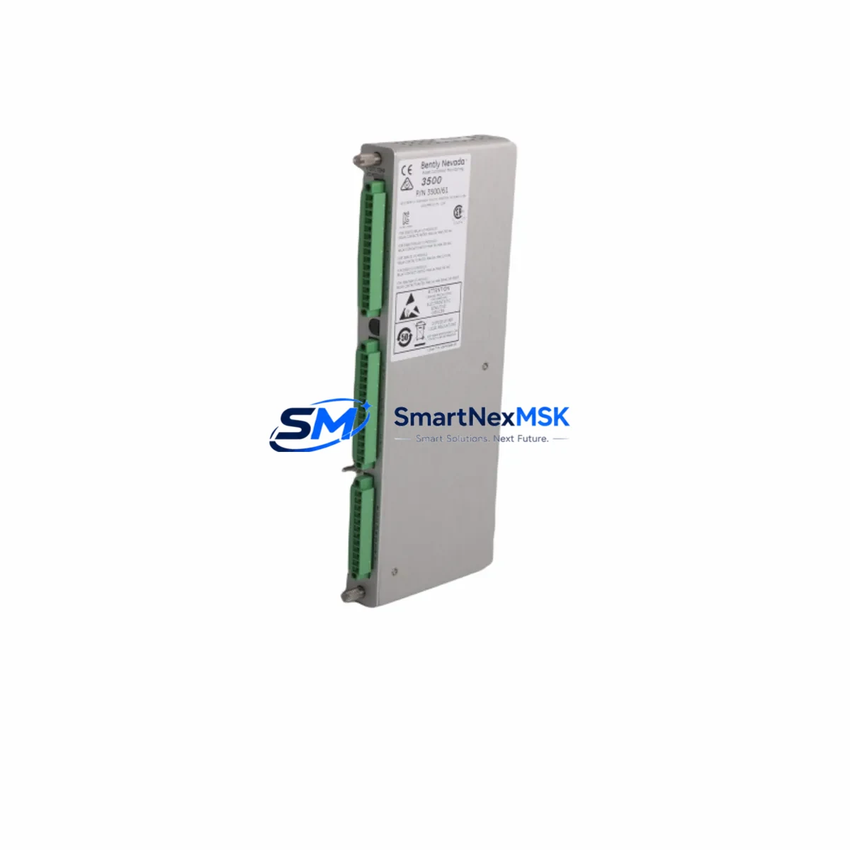
This module supports both RTD (Resistance Temperature Detector) and thermocouple (TC) input types, making it a versatile replacement across mixed-sensor installations. It slots directly into the 3500 Series rack backplane without firmware reconfiguration in most standard deployments, enabling rapid field swap-out during planned maintenance windows or emergency fault isolation. Each unit shipped by SMARTNEXMSK undergoes pre-shipment functional verification and is backed by a 12-month warranty covering manufacturing defects and operational failure under normal industrial service conditions.
Spare Maintenance Table
| Parameter | Specification / Detail |
|---|---|
| Part Number / SKU | 133819-02 |
| Brand | Bently Nevada |
| Series Compatibility | Bently Nevada 3500 Series Machinery Protection System |
| Module Function | RTD / Thermocouple (TC) Temperature I/O |
| Input Types Supported | RTD (PT100, PT1000) and Type J/K/T/E Thermocouples |
| Rack Interface | 3500 Series backplane, standard slot installation |
| Power Supply Requirement | Supplied via 3500 rack power module (e.g., 3500/15 Power Supply) |
| Operating Temperature | 0°C to +60°C (industrial control cabinet environment) |
| Mounting | Direct rack-mount, no external wiring adapter required for standard configs |
| Origin | United States (OEM) |
| Condition | Original, new or fully refurbished to OEM specification |
| Pre-Shipment Test | Functional verification performed before dispatch |
| Warranty | 12 Months — covers manufacturing defects and operational failure |
| Typical Application | Turbine, compressor, pump, and generator protection panels |
| Maintenance Interval | Inspect annually; replace on channel fault or calibration drift >±1°C |
Maintenance Planning for Continuous Operation
When scheduling replacement of the 133819-02 Temperature I/O Module, a disciplined maintenance engineer will treat the swap as an opportunity to audit the surrounding protection system rather than an isolated component change. Begin by verifying the 3500/15 Power Supply Module output voltage rails — a marginal power supply is a common root cause of intermittent I/O faults that are misdiagnosed as module failure. Confirm that the 3500/20 Rack Interface Module (RIM) is communicating cleanly with the host DCS or SCADA before reinserting the replacement 133819-02, as a degraded RIM can corrupt channel configuration data on first boot.
Inspect all field wiring terminal blocks connected to the RTD and TC sensor leads. Oxidized or loose terminations at the I/O terminal strip are a leading cause of temperature channel noise and false trips. If the installation uses signal isolators between field sensors and the 3500 rack input, verify isolator output range and loop integrity — a failed isolator will present as a module fault even after replacement. Check the 3500/32 4-Channel Relay Module associated with temperature trip outputs; relay contact wear can prevent alarm and trip signals from reaching the final control element even when the I/O module is functioning correctly.
For systems with mixed monitoring requirements, confirm that adjacent 3500/40M Proximitor/Seismic Monitor Modules and 3500/42M Proximitor/Seismic Monitor Modules are not sharing a degraded backplane segment. A failing backplane connector can cause multiple module types to report faults simultaneously, masking the true failure source. Review the 3500/22M Transient Data Interface (TDI) event log for any pre-fault transient signatures that may indicate sensor wiring issues rather than module failure. Finally, if the system communicates over Modbus TCP or OPC-DA to a plant historian or DCS, verify that the communication module — typically the 3500/92 Communication Gateway Module — is correctly mapping the restored temperature channels after module replacement to prevent data gaps in the process historian.
Site Replacement Workflow
Step 1 — Isolation and Permit: Obtain a hot-work or control system maintenance permit per site safety procedures. Notify the control room that the affected temperature channels will be in bypass during replacement. Place the relevant trip channels in maintenance override via the 3500 rack front-panel or System 1 software to prevent spurious trips during the swap.
Step 2 — Document Current Configuration: Before removing the 133819-02, use Bently Nevada System 1 or the 3500 Rack Configuration Software to export the current channel configuration (sensor type, range, trip setpoints, and delay timers). This export is your restoration baseline and eliminates reconfiguration errors after installation of the replacement module.
Step 3 — Physical Replacement: Power down the individual slot if the rack supports hot-swap inhibit, or follow the site procedure for live rack module exchange. Remove the 133819-02 by releasing the front-panel ejector levers. Inspect the backplane connector pins for damage or contamination before inserting the replacement unit. Seat the new module firmly until the ejector levers latch.
Step 4 — Configuration Restore and Verification: Re-import the saved configuration file to the replacement module. Verify all channel assignments, sensor types, and engineering unit ranges match the original. Apply a known-temperature reference source to each RTD/TC input and confirm the displayed values are within ±1°C of the reference before releasing the channels from maintenance bypass.
Step 5 — Return to Service: Remove maintenance overrides, confirm alarm and trip setpoints are active, and notify the control room that the protection system is restored to full operational status. Log the replacement in the site CMMS with the new module serial number and warranty expiry date.
Spare Parts Support FAQ
Q1: Is the 133819-02 compatible with all 3500 Series rack configurations?
The 133819-02 is designed for the Bently Nevada 3500 Series rack platform and is compatible with standard 3500 rack backplanes. Compatibility with specific rack revisions and firmware versions should be confirmed against the Bently Nevada 3500 Series product manual or by contacting SMARTNEXMSK with your rack serial number and current firmware version before ordering.
Q2: What does the 12-month warranty cover, and how is a claim initiated?
The 12-month warranty covers manufacturing defects and operational failure under normal industrial service conditions from the date of shipment. It does not cover damage resulting from incorrect installation, overvoltage events, or physical mishandling. To initiate a warranty claim, contact sales@smartnexmsk.com with your order number, a description of the fault, and photographic evidence of the failure mode. Replacement or repair will be arranged within 5 business days of claim approval.
Q3: How is the module tested before shipment?
Every 133819-02 unit undergoes a pre-shipment functional verification that includes power-on self-test, channel input simulation across the RTD and TC input ranges, and communication interface check. Units that fail any test parameter are quarantined and not dispatched. A test record is available upon request for quality-critical procurement processes.
Q4: Can SMARTNEXMSK support long-term or blanket spare parts orders for the 133819 Series?
Yes. SMARTNEXMSK supports long-term supply agreements and blanket purchase orders for the 133819 Series and broader Bently Nevada 3500 platform components. For facilities managing multiple protection racks or planning a multi-year maintenance program, contact sales@smartnexmsk.com to discuss volume pricing, reserved stock arrangements, and scheduled delivery programs that align with your planned maintenance calendar.
© 2026 SMARTNEXMSK. All rights reserved.
Original Source: https://smartnexmsk.com
Contact: sales@smartnexmsk.com | +86 18259474341


