Bently Nevada 135137-01 Retrofit-Ready Vibration Monitor for 3500 Series: Compatible Upgrade for Legacy Control Systems
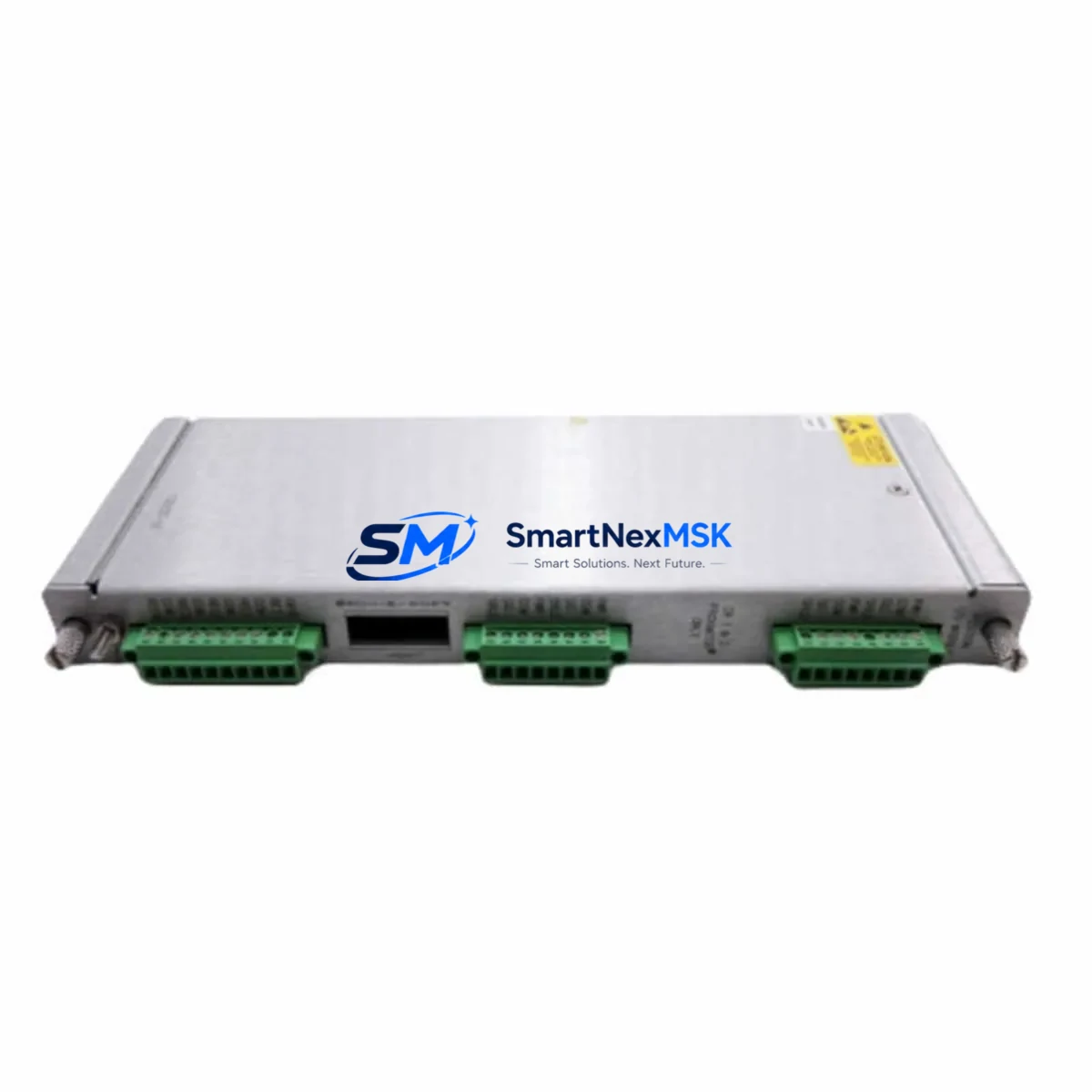
The Bently Nevada 135137-01 is a vibration monitor module engineered for the 3500 Series machinery protection system platform. As industrial facilities face increasing pressure to modernize aging condition monitoring infrastructure without full system replacement, the 135137-01 has become a critical component in retrofit and upgrade projects across power generation, oil and gas, petrochemical, and rotating machinery applications. This module provides a direct, drop-in replacement path for facilities operating legacy 3500 rack configurations, enabling engineers to restore or extend system life while maintaining compatibility with existing wiring, transducer inputs, and communication architectures.
Whether your facility is replacing a failed unit, building a spare parts inventory for a critical asset, or executing a planned control system modernization, the 135137-01 delivers the measurement accuracy, channel density, and rack interface compatibility required for seamless integration into an existing 3500 Series chassis. The module supports standard Bently Nevada transducer wiring conventions, making it suitable for direct substitution without rewiring terminal blocks or modifying field cable runs.
Upgrade Compatibility Table
| Parameter | Details |
|---|---|
| Compatible Platform | Bently Nevada 3500 Series Machinery Protection System |
| Module SKU | 135137-01 |
| Module Type | Vibration Monitor Module |
| Rack / Backplane Interface | 3500 Series standard backplane slot; compatible with 3500/05 and 3500/15 power supplies |
| Transducer Input Compatibility | Compatible with standard Bently Nevada proximity probes and velocity transducers; terminal block wiring retained |
| Communication Protocol | Compatible with 3500 Series system communication bus; supports integration with 3500/92 Communication Gateway Module for Modbus, Ethernet/IP, and OPC DA/UA output |
| Installation Requirement | Direct slot replacement; no rack modification required; module address configuration via front-panel or System 1 software |
| Replacement Recommendation | Suitable as direct replacement for failed or end-of-life 135137-01 units; verify firmware revision compatibility with existing rack configuration |
| Commissioning Notes | Confirm gap voltage, transducer sensitivity, and alarm setpoints after installation; re-validate via System 1 or rack configuration software |
| Warranty | 12-Month Warranty — covers manufacturing defects and functional failures under normal operating conditions |
Retrofit Planning for Existing Automation Systems
Successful integration of the 135137-01 into an existing 3500 Series rack begins with a thorough pre-installation audit of the current system configuration. Engineers should document the existing rack layout, including the position of the 3500/05 Power Supply Module or 3500/15 Power Supply, the slot assignments of all installed monitor modules, and the configuration of the 3500/20 Rack Interface Module, which governs system-level communication and I/O mapping to the host control system.
Before removing the failed or obsolete module, capture the full channel configuration from the System 1 software or the rack’s non-volatile memory. This includes transducer type assignments, full-scale ranges, alarm and danger setpoints, time-delay parameters, and any custom buffered output configurations. These parameters must be re-entered or restored after the 135137-01 is seated in the rack, as module replacement resets local configuration registers.
Terminal block wiring on the 3500 Series I/O module side should be inspected for corrosion, loose terminations, or insulation degradation — particularly in installations that have been in service for more than ten years. If the facility is also upgrading the 3500/92 Communication Gateway Module to enable modern Ethernet/IP or OPC UA connectivity, this is an appropriate time to review the Modbus register map and confirm that the SCADA or DCS host — whether a Honeywell Experion, Emerson DeltaV, or ABB 800xA system — is configured to poll the correct register addresses for the new module slot assignment.
For facilities running a hybrid architecture where the 3500 Series rack feeds vibration data into a broader PLC-based safety or control platform — such as a Rockwell Automation ControlLogix or Siemens S7-400 — the module address and analog output scaling must be verified against the PLC I/O configuration to prevent false alarms or missed trips during the commissioning window. If the facility uses a dedicated condition monitoring workstation running System 1 Evolution software, the asset configuration database should be updated to reflect the replacement module’s serial number and calibration date.
In multi-rack installations, where several 3500 Series chassis are networked together via the 3500/20 Rack Interface Module and a shared TDI (Transient Data Interface) bus, the replacement of a single 135137-01 should not disrupt adjacent racks — provided the system bus is not interrupted during the swap. Hot-swap capability depends on the specific rack firmware version and power supply configuration; consult the rack’s system configuration record before proceeding without a planned outage.
Downtime Control During System Migration
Minimizing unplanned downtime is the primary operational concern when replacing a vibration monitor module in a live machinery protection system. The 135137-01 replacement procedure should be planned as a scheduled maintenance window, coordinated with operations to ensure the monitored machine — typically a compressor, turbine, pump, or motor — can be safely taken offline or placed in a bypassed monitoring state for the duration of the swap.
Prior to the maintenance window, prepare a complete module swap kit: the replacement 135137-01, a calibrated laptop with System 1 or rack configuration software, the original system configuration backup file, a terminal block wiring diagram, and a calibrated gap voltage meter for transducer verification. Having the 3500/01 Rack Configuration Software pre-loaded with the existing asset configuration eliminates the need for manual re-entry of setpoints and reduces commissioning time to under 30 minutes in most cases.
During the swap, maintain the existing field wiring connections at the I/O terminal block — do not disconnect transducer cables unless inspection reveals a wiring fault. Seat the replacement 135137-01 firmly into the rack slot, confirm the module’s front-panel status LEDs indicate normal power-up, and then restore the configuration from the backup file. Verify gap voltage readings for each transducer channel before re-enabling monitoring, and confirm that alarm relay outputs are functioning correctly before returning the machine to service.
For facilities where continuous monitoring is contractually or regulatorily required, a temporary portable vibration monitoring system — such as a standalone data collector or a temporary 3500 Series portable rack — can be deployed on the machine during the swap window to maintain data continuity and satisfy audit requirements. This approach is particularly relevant in power generation and LNG facilities where machinery protection records must be uninterrupted.
Retrofit Support FAQ
Q: Is the 135137-01 a direct drop-in replacement for the original Bently Nevada module of the same part number?
A: Yes. The 135137-01 is designed as a form-fit-function replacement for the original Bently Nevada module of the same SKU. It installs into the same 3500 Series rack slot, uses the same terminal block wiring, and is compatible with the same transducer types. Minor firmware revision differences may exist; verify compatibility with your rack’s system configuration record before installation.
Q: What commissioning steps are required after installing the replacement module?
A: After seating the module, restore the channel configuration from a System 1 backup or re-enter setpoints manually. Verify transducer gap voltage for each channel using a calibrated meter. Confirm alarm and danger relay outputs are active and correctly mapped. Re-validate buffered output signals if connected to a downstream DCS or SCADA system. Full commissioning typically takes 20–45 minutes per rack.
Q: Can the 135137-01 be used in a rack that has been upgraded with a newer 3500/92 Communication Gateway Module?
A: Yes. The 135137-01 is compatible with the 3500/92 Communication Gateway Module. If the gateway has been upgraded to support Ethernet/IP or OPC UA, the monitor module’s data will be accessible via the updated protocol without modification to the module itself. Confirm that the Modbus register map or OPC tag configuration in the host system reflects the correct slot address for the replacement module.
Q: What does the 12-month warranty cover, and what is the return process?
A: The 12-month warranty covers manufacturing defects and functional failures under normal operating conditions from the date of shipment. It does not cover damage resulting from incorrect installation, overvoltage, or physical impact. To initiate a warranty claim, contact our technical support team with the module serial number, purchase order reference, and a description of the failure. Replacement or repair will be processed within the agreed lead time, and a pre-shipment functional test report is available upon request.
© 2026 SMARTNEXMSK. All rights reserved.
Original Source: https://smartnexmsk.com
Contact: sales@smartnexmsk.com | +86 18259474341


