Bently Nevada 135489-02 Retrofit-Ready I/O Module for 3500 Series: Compatible Modernization & Smooth Legacy System Upgrade
The Bently Nevada 135489-02 is a critical I/O Interface Module designed for the Bently Nevada 3500 Series machinery protection and condition monitoring platform. As industrial facilities face increasing pressure to extend the operational life of legacy control architectures while meeting modern reliability standards, the 135489-02 has become a cornerstone component in retrofit projects, discontinued spare part replacement programs, and control cabinet upgrades across oil & gas, power generation, petrochemical, and heavy manufacturing sectors.
Whether you are replacing a failed unit on an aging 3500 rack, migrating from an earlier-generation monitoring system, or expanding I/O capacity within an existing control enclosure, the 135489-02 delivers the interface compatibility, signal integrity, and installation consistency that field engineers and reliability teams depend on. This module supports the standardized backplane architecture of the 3500 Series, ensuring that existing terminal wiring, module addressing, and communication links remain intact during the changeover — minimizing engineering rework and reducing unplanned downtime.
Upgrade Compatibility Table
| Parameter | Details |
|---|---|
| SKU / Part Number | 135489-02 |
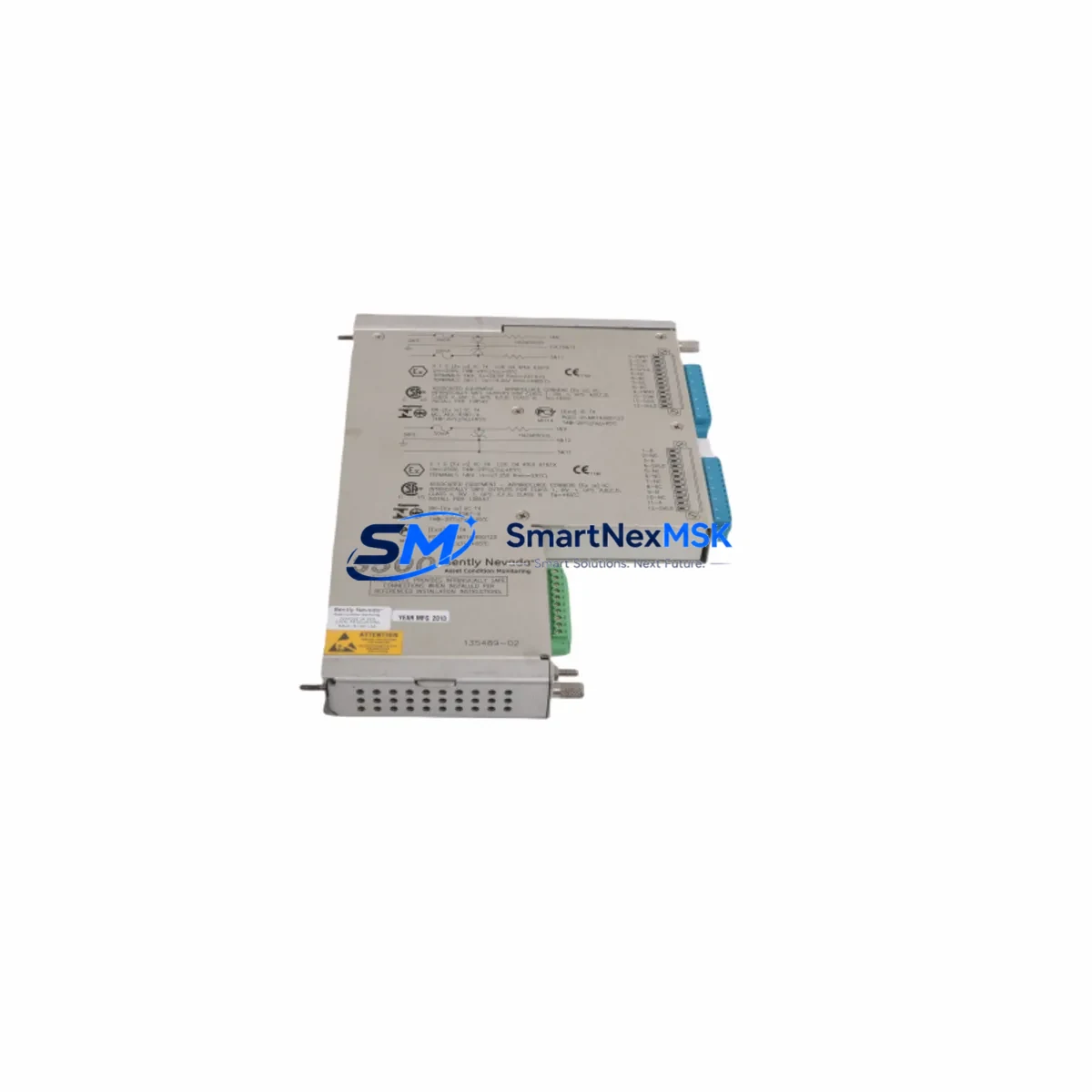
| Brand | Bently Nevada |
| Compatible Series | Bently Nevada 3500 Series Machinery Protection System |
| Module Type | I/O Interface Module |
| Backplane Interface | 3500 Series standard rack backplane — direct slot-in replacement |
| Terminal Wiring Compatibility | Compatible with existing 3500 Series terminal I/O blocks; no rewiring required in standard replacement scenarios |
| Communication Compatibility | Supports 3500 Series internal communication bus; compatible with Modbus, RS-232/RS-485 gateway configurations typical of 3500 platform |
| Installation Requirement | Rack power must be verified prior to insertion; module address configuration via front-panel DIP switches or software (system-dependent) |
| Replacement Recommendation | Direct replacement for discontinued or failed 135489-02 units; verify firmware revision compatibility with host rack controller |
| Commissioning Focus | Confirm channel assignments, I/O scaling, alarm setpoints, and communication node address after installation |
| Warranty | 12-Month Warranty — covers manufacturing defects and functional failure under normal operating conditions |
Retrofit Planning for Existing Automation Systems
Successful integration of the 135489-02 into an existing 3500 Series installation requires a structured pre-retrofit assessment. Field engineers should begin by auditing the current rack configuration, documenting the slot positions of all installed modules — including the 3500/20 Rack Interface Module, any 3500/22M Transient Data Interface units, and the 3500/32 4-Channel Relay Module — to confirm that the target slot is electrically and mechanically compatible with the 135489-02 footprint.
Power supply capacity is a non-negotiable checkpoint. The 3500/05 Power Supply Module must be verified to provide sufficient current headroom after the new I/O module is added to the rack load. In systems where multiple I/O expansion modules are already installed, a load calculation should be performed before proceeding. If the existing power supply is operating near its rated output, a parallel or upgraded 3500/05-01 redundant power supply configuration should be considered before the retrofit is finalized.
Terminal block wiring is the next critical step. The 135489-02 interfaces with the 3500 Series I/O terminal blocks, and technicians must confirm that the existing field wiring — sensor cables from proximity probes, velocity transducers, or process transmitters — is correctly mapped to the new module’s channel assignments. Any deviation in channel mapping will require corresponding updates to the System 1 Evolution software configuration or the legacy Bently Nevada Data Manager database, depending on the monitoring software version in use at the facility.
For sites running communication gateways between the 3500 rack and a DCS or SCADA platform — such as a 3500/92 Communication Gateway Module using Modbus TCP or OPC — the node address and register map of the replacement 135489-02 must be validated against the existing gateway configuration. Any mismatch in register mapping will cause data loss or alarm suppression at the supervisory level, which is unacceptable in machinery protection applications.
HMI screen updates are often overlooked during I/O module replacements. If the facility uses a dedicated operator interface — whether a standalone HMI panel or a DCS faceplate — the channel tag names, engineering unit scaling, and alarm threshold displays linked to the 135489-02 channels must be reviewed and updated to reflect the new module’s configuration. This is particularly important when replacing a module that had custom channel scaling or non-standard alarm logic programmed into the original unit.
Finally, for sites that also manage vibration monitoring through companion modules such as the 3500/40M Proximitor/Seismic Monitor or the 3500/42M Proximitor/Seismic Monitor, the retrofit plan should include a cross-check of the overall rack I/O map to ensure that the 135489-02 replacement does not inadvertently affect adjacent module addressing or shared backplane communication resources.
Downtime Control During System Migration
Minimizing production interruption during a 3500 Series I/O module replacement is achievable with disciplined pre-work and a clear on-site execution protocol. The recommended approach is to complete all configuration preparation — including software backup of the existing rack configuration using Rack Configuration Software (RCS), export of all channel parameters, alarm setpoints, and communication settings — before the maintenance window begins. This ensures that if any unexpected issue arises during the physical swap, the original configuration can be restored rapidly without relying on memory or incomplete field notes.
During the replacement window, the sequence should follow: rack power isolation (or hot-swap procedure if the rack supports it), physical removal of the failed or obsolete 135489-02, insertion of the replacement module into the correct slot, and immediate verification of backplane communication status via the rack’s front-panel status LEDs or the RCS software connection. Once communication is confirmed, channel-by-channel functional verification should be performed — checking that each input channel is receiving the expected signal from its connected transducer and that output relay states match the programmed logic.
For facilities where continuous machinery protection coverage is mandatory — such as rotating equipment on critical compressor trains or turbine-generator sets — a temporary bypass or parallel monitoring arrangement using a portable vibration analyzer should be in place during the swap window. This preserves protection coverage for the machine while the permanent monitoring channel is briefly offline, satisfying both safety requirements and insurance obligations without requiring a full machine shutdown.
After the replacement is complete and all channels are verified, the updated rack configuration should be saved and archived, and a post-retrofit functional test report should be generated documenting the as-found and as-left conditions for each channel. This documentation supports future maintenance planning, regulatory compliance, and warranty claim processing if required within the 12-month warranty period.
Retrofit Support FAQ
Q1: Is the 135489-02 a direct drop-in replacement for the original Bently Nevada 135489-02 installed in my 3500 rack?
A: In the vast majority of 3500 Series installations, yes. The 135489-02 is designed to occupy the same rack slot, use the same backplane connector, and interface with the same terminal I/O blocks as the original unit. However, you should verify the firmware revision of your rack controller and confirm that the replacement module’s hardware revision is compatible. If your system is running an older version of the Rack Configuration Software, a firmware update may be recommended before commissioning the new module.
Q2: Do I need to rewire the terminal blocks when replacing the 135489-02?
A: In standard replacement scenarios, no rewiring is required. The 135489-02 uses the same terminal block interface as the original module, so existing field wiring from proximity probes, velocity transducers, or process transmitters can remain connected. You should, however, inspect the terminal block for any signs of corrosion, loose connections, or insulation damage before reinstalling, as these conditions can cause intermittent faults that are difficult to diagnose after the new module is in service.
Q3: How do I verify communication compatibility between the replacement 135489-02 and my existing DCS or SCADA system?
A: After physical installation, connect to the rack using the Rack Configuration Software and confirm that the module is recognized on the backplane. Then verify the communication gateway configuration — particularly the Modbus register map or OPC tag assignments — to ensure that the replacement module’s channel data is being correctly transmitted to the supervisory system. A live data comparison between the RCS channel display and the DCS/SCADA operator screen is the most reliable verification method before returning the machine to normal monitored operation.
Q4: What does the 12-month warranty cover, and how is a warranty claim processed?
A: The 12-month warranty covers manufacturing defects and functional failures that occur under normal operating conditions within one year of the shipment date. It does not cover damage resulting from incorrect installation, overvoltage conditions, physical impact, or unauthorized modification. To initiate a warranty claim, contact our sales team with the original order reference, a description of the failure symptom, and the module’s serial number. We will arrange for return shipment, technical evaluation, and replacement or repair as appropriate. All units are functionally tested prior to shipment to minimize the risk of DOA (dead-on-arrival) failures.
© 2026 SMARTNEXMSK. All rights reserved.
Original Source: https://smartnexmsk.com
Contact: sales@smartnexmsk.com | +86 18259474341


