Bently Nevada 149992-02 Spare for 3500 Automation: Relay Output Replacement & Downtime Risk Control
The Bently Nevada 149992-02 is an original relay output module designed for the 3500 Series Machinery Protection System — one of the most widely deployed vibration and condition monitoring platforms in rotating equipment facilities worldwide. When a relay output module fails or degrades, the consequences extend far beyond a single I/O channel: alarm annunciation, trip relay logic, and protective shutdown sequences all depend on the integrity of this component. Sourcing a verified, tested replacement is the first step in restoring system confidence and minimizing unplanned downtime.
For maintenance engineers managing turbines, compressors, pumps, and generators, the 149992-02 sits at the intersection of machinery protection and plant safety. Its relay contacts interface directly with DCS trip inputs, emergency shutdown systems (ESD), and control room annunciator panels. A degraded or failed module can mask real machinery faults or generate spurious trips — both outcomes are operationally unacceptable. Keeping a qualified spare on the shelf is not optional; it is a fundamental element of any serious predictive maintenance or reliability-centered maintenance (RCM) program.
Spare Maintenance Table
| Parameter | Specification / Detail |
|---|---|
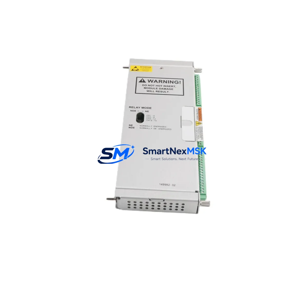
| Part Number | 149992-02 |
| Brand | Bently Nevada |
| Series | 3500 Machinery Protection System |
| Module Type | Relay Output Module |
| Relay Contacts | Form C (SPDT), normally energized / de-energized configurable |
| Contact Rating | 5 A @ 250 VAC / 30 VDC (resistive load) |
| Number of Relay Channels | 4 independent relay outputs |
| Backplane Compatibility | 3500/20 Rack (standard and enhanced) |
| Power Supply Compatibility | 3500/15 Power Supply Module (single or redundant) |
| Operating Temperature | 0°C to +60°C |
| Humidity | 5% to 95% RH, non-condensing |
| Installation | Hot-swap capable within 3500 rack architecture |
| Origin | USA (Original Bently Nevada / Baker Hughes) |
| Condition | Original spare, function-tested before shipment |
| Warranty | 12 Months |
| Shipping | DHL / FedEx Express, worldwide; ESD-safe packaging |
| Lead Time | In-stock: ships within 1–3 business days |
| Application | Turbines, compressors, pumps, generators, rotating machinery |
| Maintenance Recommendation | Inspect relay contacts and wiring annually; replace at first sign of contact wear or intermittent trip behavior |
Maintenance Planning for Continuous Operation
When replacing the 149992-02 Relay Output Module during a planned or emergency maintenance event, a thorough inspection of the surrounding 3500 rack components is strongly recommended. Relay output failures rarely occur in isolation — they are often preceded or accompanied by degradation in adjacent modules or interconnecting wiring.
Begin by verifying the 3500/15 Power Supply Module output voltage and ripple. An unstable rack power supply is a common root cause of relay contact chatter and premature coil wear. If the rack uses a redundant power supply configuration, confirm that both supplies are healthy and that the changeover relay is functioning correctly.
Next, inspect the 3500/20 Rack and Backplane for signs of corrosion, loose module connectors, or damaged backplane traces. The relay output module communicates with monitor modules — such as the 3500/40M Proximitor/Seismic Monitor or the 3500/42M Proximitor/Seismic Monitor — via the backplane bus. Any backplane integrity issue will affect relay logic even after a module swap.
Review the 3500/92 Communication Gateway Module or 3500/93 Communication Module configuration to confirm that relay output assignments and trip multiply settings are correctly mapped after reinstallation. Misconfigured relay assignments are a frequent post-maintenance commissioning error that can delay return-to-service.
For facilities using Keyphasor signals, verify that the 3500/25 Keyphasor Module is providing a clean reference signal. A degraded Keyphasor input can cause erratic speed-based relay logic, leading to nuisance trips or missed alarms on the relay output channels.
Inspect all field wiring terminations at the 3500 I/O Module terminal blocks. Loose or corroded terminals on the relay output wiring — particularly on trip relay circuits feeding ESD panels or DCS digital inputs — are a leading cause of intermittent relay faults that are difficult to reproduce during bench testing. Use a calibrated torque screwdriver and verify continuity with a loop tester before returning the system to service.
If the 3500 rack interfaces with a System 1 Evolution or System 1 Condition Monitoring Software platform, confirm that the relay output module’s channel configuration is correctly reflected in the software after the swap. Mismatched channel assignments between the hardware and the monitoring software can result in incorrect alarm routing.
Finally, for control cabinets that also house signal isolators (such as those used to interface 3500 relay outputs with third-party DCS systems), verify isolator input voltage ranges and output signal integrity. A relay output module replacement is an ideal opportunity to inspect and clean all isolator terminals and confirm that isolation barriers are functioning correctly.
Site Replacement Workflow
Step 1 — Pre-Replacement Verification: Confirm the exact part number (149992-02) against the rack slot label and the 3500 rack configuration record. Verify that the replacement module’s firmware revision is compatible with the installed rack firmware. Document the current relay output assignments, trip setpoints, and time delays from the System 1 software or the rack configuration file before proceeding.
Step 2 — Safe Isolation: Coordinate with the control room to place the affected machinery protection channels in bypass mode (if plant procedures permit) before removing the module. This prevents spurious trips during the swap. Confirm bypass status with the DCS operator and log the bypass in the maintenance management system.
Step 3 — Module Removal and Inspection: Remove the 149992-02 from the rack slot. Inspect the backplane connector pins for damage or contamination. Inspect the removed module for signs of overheating, relay contact arcing, or component damage. Retain the failed module for failure analysis if required by your reliability program.
Step 4 — Installation and Configuration: Insert the replacement 149992-02 into the rack slot. The 3500 rack architecture supports hot-swap for relay output modules — the module will initialize automatically and load its configuration from the rack’s non-volatile memory. Verify that all relay output LEDs indicate correct status after initialization.
Step 5 — Functional Test: Using the System 1 software or the rack’s front-panel interface, perform a relay output functional test on each channel. Verify that trip relay contacts operate correctly and that the DCS or ESD panel receives the expected digital input signals. Confirm alarm annunciation in the control room.
Step 6 — Return to Service: Remove the bypass, confirm normal monitoring status in System 1, and update the maintenance record with the replacement date, module serial number, and test results. Schedule the next inspection interval per your RCM program.
Spare Parts Support FAQ
Q1: Is the 149992-02 still available as a new original spare, or only as a refurbished unit?
We supply original Bently Nevada 149992-02 modules sourced from authorized distribution channels and verified surplus inventory. Each unit undergoes functional testing prior to shipment. The condition (new original or tested surplus) is clearly stated in the order confirmation. All units carry a 12-month warranty regardless of condition grade.
Q2: How do I verify compatibility with my existing 3500 rack before ordering?
The 149992-02 is compatible with standard 3500/20 racks. To confirm compatibility, provide your rack model number, current firmware revision, and the slot position of the existing relay output module. Our technical team will verify compatibility and advise on any firmware or configuration considerations before shipment.
Q3: What testing is performed before the module ships?
Each 149992-02 is tested for relay contact continuity, coil resistance, backplane connector integrity, and power consumption within specification. Modules are shipped in ESD-safe packaging with a test report. If your facility requires a specific acceptance test procedure (ATP), contact us to discuss custom pre-shipment testing arrangements.
Q4: What is your recommended spare parts stocking strategy for the 3500 Series?
For facilities with multiple 3500 racks protecting critical rotating equipment, we recommend maintaining at least one 149992-02 relay output module per rack as a cold standby spare. For plants with extended lead times from OEM channels or those operating legacy 3500 systems beyond the standard product lifecycle, a minimum stock of two units per site is advisable. Pairing the relay output module spare with a 3500/15 power supply spare and a 3500/40M or 3500/42M monitor module spare provides comprehensive coverage for the most common 3500 rack failure modes.
© 2026 SMARTNEXMSK. All rights reserved.
Original Source: https://smartnexmsk.com
Contact: sales@smartnexmsk.com | +86 18259474341


