Bently Nevada 172109-01 Retrofit-Ready Rack Interface Card for 3500 Series Control Systems
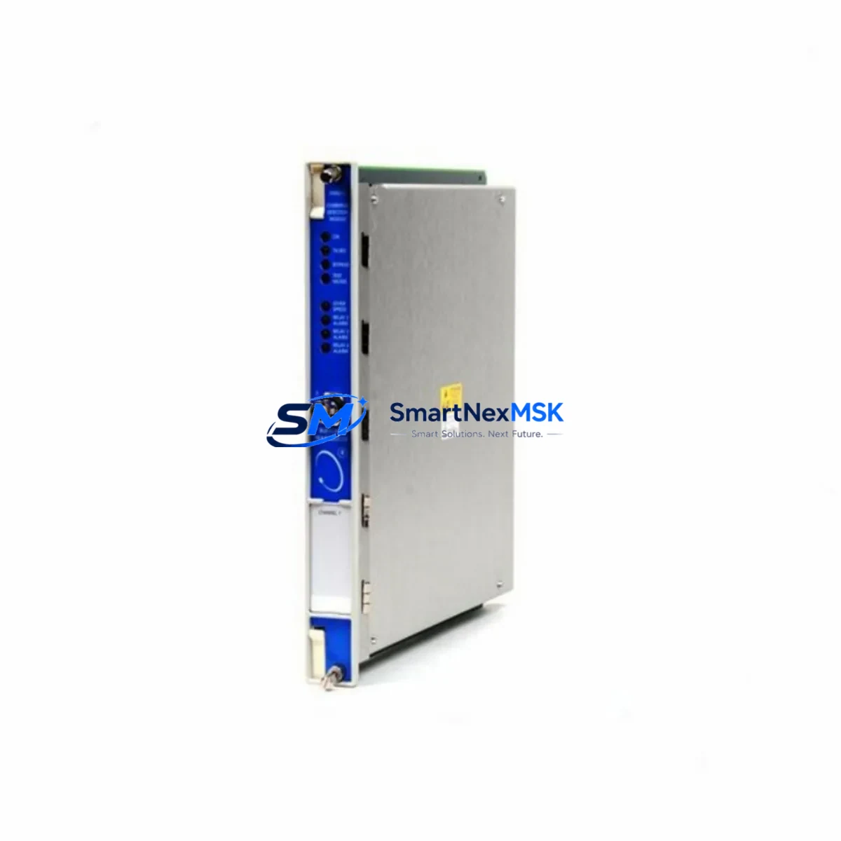
The Bently Nevada 172109-01 is a Rack Interface Card (RIC) designed for the 3500 Series machinery protection and condition monitoring platform. As legacy 3500 Series installations age across petrochemical, power generation, and rotating equipment facilities, the 172109-01 has become a critical retrofit component for engineers managing end-of-life hardware transitions, spare parts shortages, and control system modernization projects. SMARTNEXMSK maintains verified stock of the 172109-01 with full functional testing, 12-month warranty coverage, and rapid global dispatch to minimize unplanned downtime.
Upgrade Compatibility Table
| Parameter | Details |
|---|---|
| Part Number | 172109-01 |
| Brand | Bently Nevada |
| Series | 3500 Series Machinery Protection System |
| Module Function | Rack Interface Card — system communication backbone between rack and host |
| Backplane Interface | 3500 Series standard backplane; direct slot-compatible installation |
| Communication Compatibility | RS-232, RS-422/485, Ethernet (model-dependent); verify host DCS/SCADA protocol before swap |
| Power Requirement | Supplied via 3500 rack power module (e.g., 3500/15 Power Supply); no external wiring required |
| Replacement Recommendation | Direct drop-in for failed or end-of-life 172109-01 units; confirm firmware revision compatibility with System 1 software |
| Commissioning Notes | Re-configure node address and communication parameters via Rack Configuration Utility after installation |
| Warranty | 12 Months — covers functional failure under normal operating conditions |
| Origin | USA (Bently Nevada / Baker Hughes) |
| Shipping | In-stock; global express dispatch within 24–48 hours |
Retrofit Planning for Existing Automation Systems
Replacing the 172109-01 in an operational 3500 Series rack requires careful pre-outage planning. The Rack Interface Card serves as the communication bridge between the 3500 rack and the plant’s DCS, SCADA, or System 1 condition monitoring software. Before scheduling the swap, engineers should audit the existing rack configuration — including the 3500/20 Rack Configuration Module settings, the installed I/O module addresses, and the active communication protocol in use (Modbus RTU, Modbus TCP, or proprietary Bently Nevada protocol).
In a typical 3500 Series rack, the 172109-01 coexists with a range of monitoring and I/O modules. Common co-installed hardware includes the 3500/40M Proximitor/Seismic Monitor for radial vibration channels, the 3500/42M Proximitor/Seismic Monitor for axial position and thrust, and the 3500/50M Tachometer Module for speed and phase reference signals. The 3500/22M Transient Data Interface is frequently present in facilities running System 1 software for waveform capture and trending. All of these modules communicate through the backplane, and the 172109-01 must be correctly addressed and configured to maintain uninterrupted data flow to each.
Terminal wiring on the 172109-01 is limited to the host communication port — typically a DB-9 or RJ-45 connector depending on the revision. Verify the cable type and pinout against the existing host interface before the outage window. If the plant is migrating from a serial RS-232 or RS-422 link to an Ethernet-based connection, a 3500/92 Communication Gateway Module may be required in parallel to bridge legacy field devices during the transition period. Similarly, if the facility operates a Bently Nevada 3300 Series rack alongside the 3500 platform, protocol mapping between the two systems must be validated before the new RIC is brought online.
For facilities using a Honeywell Experion PKS or Emerson DeltaV DCS as the host system, confirm that the OPC server or Modbus driver configuration reflects the new module’s node address. Mismatched addresses are the most common cause of communication loss after a rack interface card replacement. The Bently Nevada System 1 Evolution software provides a rack configuration export function — back up the existing configuration file before the outage and use it as the baseline for post-swap verification.
If the retrofit scope extends beyond a single card replacement to a full rack upgrade, consider whether the existing 3500/15 Power Supply Module has sufficient capacity to support any additional I/O modules being added. Power budget calculations should account for all installed modules, including spare slots planned for future expansion. A 3500/05 Rack (3-slot) or 3500/05-01-02-00-00 Rack (14-slot) chassis may need to be evaluated if the existing rack is at capacity.
Downtime Control During System Migration
Minimizing downtime during a 172109-01 replacement begins with a structured pre-outage checklist. First, export and archive the full rack configuration from the Rack Configuration Utility — this file captures all module addresses, alarm setpoints, transducer types, and communication parameters. Second, document the current System 1 or DCS tag mapping so that post-swap verification can be completed against a known baseline rather than relying on memory or legacy drawings.
The physical swap of the 172109-01 is non-destructive to field wiring — all transducer cables connect to the individual monitor modules (e.g., 3500/40M, 3500/50M), not to the Rack Interface Card itself. This means the outage window for the card swap can be as short as 15–30 minutes if the replacement unit is pre-configured and the communication parameters are documented in advance. After installation, restore the rack configuration file, verify that all module status LEDs return to normal, and confirm that System 1 or the DCS host is receiving live data on all channels before releasing the equipment back to operations.
For critical rotating equipment — compressors, turbines, pumps — where continuous monitoring is contractually or safety-mandated, coordinate with the operations team to arrange a brief controlled shutdown or a hot-standby monitoring arrangement using portable vibration analyzers during the swap window. SMARTNEXMSK can provide pre-tested, pre-configured 172109-01 units with the firmware revision specified by the customer to further compress commissioning time on site.
Retrofit Support FAQ
Q1: Is the 172109-01 a direct drop-in replacement for all 3500 Series rack configurations?
The 172109-01 is slot-compatible with standard 3500 Series racks. However, firmware revision and communication protocol settings must match the host system’s expectations. Confirm the revision level of the failed unit and request a matching or compatible revision when ordering. SMARTNEXMSK provides revision documentation with each shipment.
Q2: What wiring changes are required when installing the 172109-01?
Field transducer wiring connects to individual monitor modules, not to the Rack Interface Card. The only wiring on the 172109-01 is the host communication cable (RS-232, RS-422, or Ethernet). Verify cable type, pinout, and connector standard before the outage. No terminal block rewiring is required for a like-for-like replacement.
Q3: How is compatibility with System 1 software verified after installation?
After installing the 172109-01 and restoring the rack configuration file, open System 1 and confirm that all rack nodes appear online and that live vibration, position, and speed data is populating correctly on all configured channels. Check the System 1 event log for any communication fault alarms. If faults persist, verify the node address and baud rate settings in the Rack Configuration Utility match the System 1 driver configuration.
Q4: What does the 12-month warranty cover, and what is the return process?
The 12-month warranty covers functional failure of the 172109-01 under normal operating conditions, including communication failures, backplane interface faults, and module non-recognition by the rack. Physical damage caused by incorrect installation, overvoltage, or environmental exposure is excluded. To initiate a warranty claim, contact SMARTNEXMSK with the order reference and a description of the fault. A replacement unit will be dispatched upon fault confirmation, with return shipping instructions provided.
© 2026 SMARTNEXMSK. All rights reserved.
Original Source: https://smartnexmsk.com
Contact: sales@smartnexmsk.com | +86 18259474341


