Bently Nevada 177230-01-02-05 Maintenance Spare 3500 Series: Spare Replacement & Industrial Downtime Risk Control
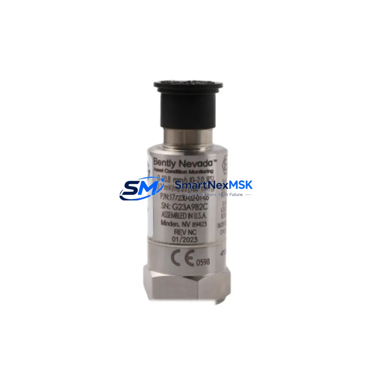
The Bently Nevada 177230-01-02-05 is an original seismic velocity transmitter module designed for the 3500 Series machinery protection system — one of the most widely deployed continuous vibration monitoring platforms in rotating equipment facilities worldwide. For maintenance engineers managing turbines, compressors, pumps, and generators, this module is a critical line-of-defense component. When it fails or degrades, the entire vibration channel goes blind, leaving rotating machinery unprotected and exposing the plant to unplanned shutdown risk.
Sourced as an original spare, the 177230-01-02-05 is fully compatible with the 3500 rack architecture and integrates directly with the 3500/20 rack interface module and 3500/22M transient data interface. It accepts velocity transducer inputs and converts seismic signals into 4–20 mA analog outputs and relay-driven alarm/danger trip signals. Maintenance teams replacing this module can restore full channel protection without firmware reconfiguration, provided the rack configuration file is preserved in the 3500 System Configuration Utility.
Spare Maintenance Table
| Parameter | Specification / Detail |
|---|---|
| Part Number | 177230-01-02-05 |
| Brand | Bently Nevada |
| Series | 3500 Machinery Protection System |
| Module Type | Seismic Velocity Transmitter Module |
| Input Signal | Velocity transducer (seismic) |
| Output | 4–20 mA analog; relay alarm/danger contacts |
| Rack Compatibility | 3500/20 Rack Interface Module; 3500 Series backplane |
| Configuration Tool | Bently Nevada 3500 System Configuration Utility |
| Operating Temperature | 0°C to 65°C (standard industrial environment) |
| Mounting | 3500 Series modular rack slot (direct plug-in) |
| Origin | USA |
| Condition | Original spare, tested before shipment |
| Warranty | 12 months from date of shipment |
| Application | Turbines, compressors, pumps, generators, fans |
| Maintenance Recommendation | Replace as part of planned channel verification or after alarm/danger relay fault |
Maintenance Planning for Continuous Operation
When a 177230-01-02-05 seismic velocity transmitter module is flagged for replacement during a planned outage or emergency shutdown, experienced maintenance engineers know that the module itself is rarely the only component requiring attention. A thorough inspection of the associated measurement chain and control cabinet is essential to prevent repeat failures and ensure the restored channel performs reliably.
Begin by verifying the 3500/20 Rack Interface Module — the backplane communication bridge between the transmitter module and the system controller. A degraded rack interface can cause false readings even after a new transmitter module is installed. Next, inspect the 3500/15 Power Supply Module (or its redundant pair if configured), as voltage instability is a leading cause of premature module failure in seismic monitoring channels. Check the DC bus output under load and compare against the module’s rated supply tolerance.
The field wiring from the velocity transducer to the module terminal block should be inspected for insulation breakdown, shield continuity, and connector corrosion — particularly in high-vibration or high-humidity environments. If the plant uses Bently Nevada 330500 or 330104 proximity transducers in adjacent channels, verify their gap voltage and sensitivity calibration during the same maintenance window to avoid a second unplanned outage shortly after restart.
For facilities running mixed monitoring architectures, the 3500/22M Transient Data Interface should be checked for buffer integrity and communication link status with the System 1 software platform. If the plant uses 3500/32 4-Channel Relay Module for trip logic, confirm that the relay setpoints and time delays are correctly mapped to the restored seismic channel before returning the machine to service.
Procurement engineers building a spare parts inventory for 3500 Series systems should also stock the 3500/25 Enhanced Keyphasor Module for phase reference continuity, and consider holding a spare 3500/42M Proximitor/Seismic Monitor for facilities where both proximity and seismic channels share the same rack. Terminal blocks, fuse holders, and DIN rail-mounted signal isolators within the control cabinet should be inspected and replaced on a scheduled basis — these low-cost components are frequently overlooked but are common root causes of intermittent channel faults that are misdiagnosed as module failures.
Site Replacement Workflow
Replacing the 177230-01-02-05 on-site is a straightforward procedure when the correct spare is on hand and the rack configuration is documented. The following workflow is recommended to minimize downtime and ensure system compatibility:
Step 1 — Pre-replacement verification: Confirm the replacement module part number matches the installed module exactly, including the option codes in the suffix (-01-02-05). Option codes define channel count, output type, and alarm relay configuration. Installing a module with a different suffix may require rack reconfiguration and could trigger false alarms during startup.
Step 2 — Configuration backup: Before removing the existing module, export the rack configuration file using the 3500 System Configuration Utility. Store the backup on a local engineering workstation and a network share. This file contains all setpoint, scaling, and relay logic data for the channel.
Step 3 — Hot-swap or cold-swap: The 3500 Series supports hot-swap replacement for most monitor modules without powering down the rack, provided the rack is not in a single-supply configuration. Confirm with the plant safety procedure before proceeding. Slide the module out, insert the replacement, and allow the rack to re-initialize the channel — typically within 30 seconds.
Step 4 — Configuration restore and verification: Download the saved configuration file to the new module. Verify all setpoints, full-scale ranges, and relay assignments match the pre-replacement values. Apply a known reference signal to the transducer input and confirm the module output and alarm relay behavior are correct before releasing the machine to operations.
Step 5 — Documentation: Record the replacement in the plant maintenance management system (CMMS), including the new module serial number, installation date, and post-replacement test results. This data supports future predictive maintenance decisions and warranty tracking.
Spare Parts Support FAQ
Q1: Is the 177230-01-02-05 compatible with all 3500 Series racks?
The 177230-01-02-05 is designed for the Bently Nevada 3500 Series modular rack platform. Compatibility depends on the rack slot assignment and the system configuration. The option code suffix (-01-02-05) defines specific channel and output configurations — always verify the suffix matches your existing installed module before ordering. If you are replacing a legacy variant with a different suffix, contact our technical team for cross-reference confirmation.
Q2: What does the 12-month warranty cover?
All modules supplied by SMARTNEXMSK carry a 12-month warranty from the date of shipment. The warranty covers manufacturing defects and functional failures under normal operating conditions. Each unit undergoes functional testing prior to dispatch. Warranty claims are supported with a return merchandise authorization (RMA) process and replacement shipment within agreed lead times.
Q3: How quickly can the module be shipped, and what documentation is provided?
In-stock modules are typically dispatched within 1–3 business days. Each shipment includes a packing list, test record, and country-of-origin documentation. Express freight options are available for emergency shutdown recovery situations. Contact sales@smartnexmsk.com with your urgency level and destination for a freight quote.
Q4: Can SMARTNEXMSK support long-term supply for legacy 3500 Series components?
Yes. SMARTNEXMSK maintains a dedicated inventory program for Bently Nevada 3500 Series spare parts to support plants operating legacy systems beyond the original manufacturer’s active production lifecycle. We can establish blanket purchase orders, consignment stock arrangements, or scheduled delivery programs to ensure your maintenance team always has critical spares on hand without overstocking capital.
© 2026 SMARTNEXMSK. All rights reserved.
Original Source: https://smartnexmsk.com
Contact: sales@smartnexmsk.com | +86 18259474341


