Bently Nevada 177230-02-01-CN Maintenance-Ready Spare 3500 Automation
The Bently Nevada 177230-02-01-CN is an original seismic velocity transmitter engineered for the 3500 Series machinery protection system — one of the most widely deployed continuous monitoring platforms in rotating equipment facilities worldwide. For maintenance engineers managing turbines, compressors, pumps, and gearboxes, this transmitter is a critical front-line component: it converts mechanical vibration into a 4–20 mA analog signal that feeds directly into the 3500 rack’s monitoring and trip logic. When this unit degrades or fails, the entire vibration channel goes dark, leaving the machine unprotected and the plant exposed to unplanned shutdown risk.
Sourced as an original spare, the 177230-02-01-CN carries full factory specifications and is subject to pre-shipment functional testing before dispatch. Each unit is backed by a 12-month warranty covering manufacturing defects and electrical performance. For procurement engineers building a resilient spare parts inventory, stocking at least one verified unit of this transmitter is standard practice in any facility running Bently Nevada 3500 Series racks.
Spare Maintenance Table
| Parameter | Specification |
|---|---|
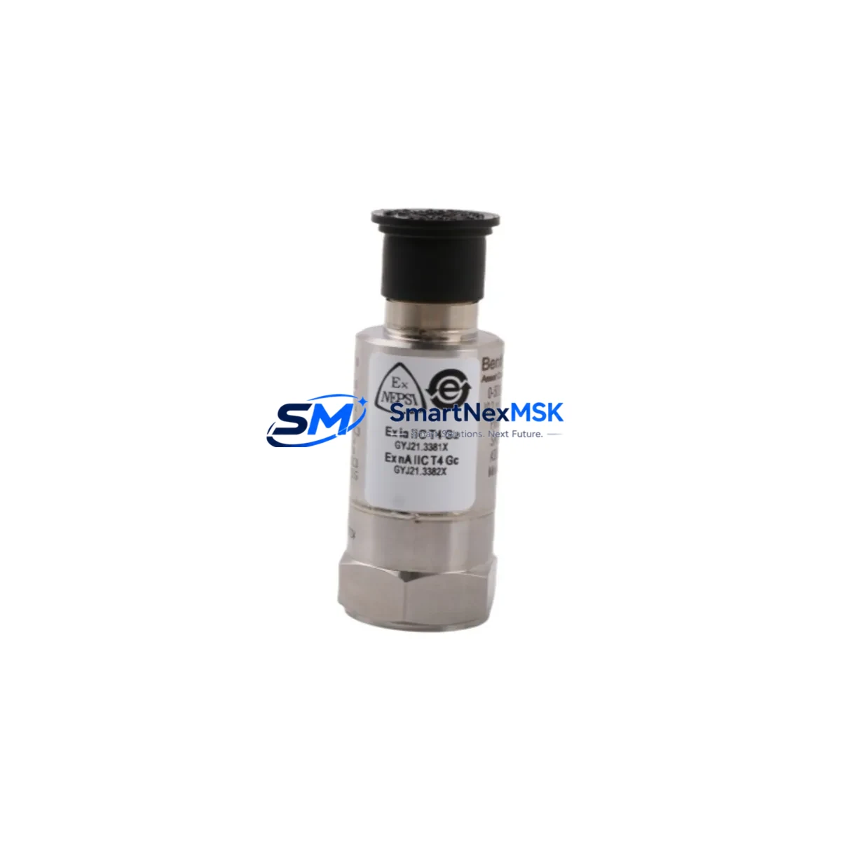
| Part Number | 177230-02-01-CN |
| Brand | Bently Nevada |
| Series | 3500 Series Machinery Protection System |
| Product Type | Seismic Velocity Transmitter |
| Output Signal | 4–20 mA analog |
| Measurement | Seismic velocity (vibration) |
| Compatibility | Bently Nevada 3500 rack system; compatible with 3500/42M, 3500/44M, 3500/45 monitor modules |
| Installation | Field-mount; standard industrial enclosure; M20 or NPT conduit entry |
| Operating Environment | Industrial plant floor; suitable for high-vibration, high-temperature environments |
| Origin | USA (Original Bently Nevada) |
| Warranty | 12 Months — covers manufacturing defects and electrical performance |
| Pre-shipment Test | Functional output verification before dispatch |
| Maintenance Interval | Inspect every 12 months or per OEM PM schedule |
| Replacement Scenario | Signal drift, open circuit, physical damage, channel alarm/trip |
Maintenance Planning for Continuous Operation
Replacing the 177230-02-01-CN in the field is rarely an isolated task. A seismic velocity transmitter sits at the intersection of mechanical, electrical, and control system domains — and a thorough replacement procedure demands that the maintenance team inspect and verify the health of every connected component before returning the channel to service.
Begin with the 3500 rack power supply module (such as the 3500/15 or 3500/20 power supply). A marginal power supply can introduce noise into the 4–20 mA loop, causing false readings even after a transmitter swap. Verify output voltage stability under load before commissioning the new unit. Next, inspect the field wiring and shielded cable run from the transmitter junction box back to the rack. Damaged insulation, corroded terminals, or improper shield grounding are common root causes of signal degradation that get misdiagnosed as transmitter failure.
At the rack level, confirm the health of the 3500/42M or 3500/44M monitor module that receives the transmitter signal. If the channel has been in alarm or trip state, the monitor card’s input circuitry should be verified with a loop calibrator before assuming the new transmitter is the sole fix. In parallel, check the 3500/32 relay output module — if the vibration channel drives a trip relay, confirm that relay coil resistance and contact continuity are within spec.
For facilities using Keyphasor modules (3500/25 or 3500/17) alongside seismic channels, verify that the Keyphasor signal is clean and phase-referenced correctly, as some 3500 configurations use Keyphasor data to qualify seismic readings. Also inspect the terminal block assemblies and I/O marshalling panels in the control cabinet — loose or oxidized terminations at the field terminal strips are a frequent source of intermittent channel faults.
If the plant uses a DCS integration layer (such as a Honeywell C300 or Emerson DeltaV I/O card) to receive the 4–20 mA signal from the 3500 rack’s buffered output, verify that the DCS analog input card is reading correctly after the transmitter replacement. A signal isolator or loop-powered isolator in the signal path should also be checked for drift, particularly in older installations where isolators may be approaching end of service life.
Finally, for sites running System 1 Evolution or Orbit software for condition monitoring, confirm that the channel configuration, engineering units, and alarm setpoints are correctly mapped to the new transmitter’s output range before returning the machine to normal operation.
Site Replacement Workflow
The 177230-02-01-CN is a direct replacement for earlier Bently Nevada seismic velocity transmitter variants used in 3500 Series installations. The replacement workflow is designed to minimize downtime and maintain system compatibility throughout the process.
Step 1 — Pre-replacement verification: Confirm the existing transmitter’s part number and revision against the rack configuration record. Verify that the replacement unit’s output range and loop impedance match the monitor module’s input specification. Use a loop calibrator to simulate the 4–20 mA signal at the rack input before physically swapping the transmitter — this confirms the monitor card and wiring are functional.
Step 2 — Safe isolation: Follow site LOTO (Lockout/Tagout) procedures. Isolate the transmitter loop at the field junction box. Do not de-energize the entire 3500 rack unless required by site procedure — most 3500 racks support hot-swap of field devices without affecting other channels.
Step 3 — Physical replacement: Remove the old transmitter, inspect the mounting surface and conduit entry for corrosion or mechanical damage. Install the 177230-02-01-CN, torque mounting hardware to specification, and reconnect field wiring with correct polarity. Verify shield grounding at one end only.
Step 4 — Loop commissioning: Restore loop power and verify the 4–20 mA output at the rack terminal. Confirm the System 1 or DCS trend display shows a live, noise-free signal. Check that the channel alarm and trip setpoints are active and correctly configured.
Step 5 — Return to service: Document the replacement in the site maintenance management system (CMMS), update the spare parts inventory record, and schedule the next inspection interval per the OEM PM schedule.
Spare Parts Support FAQ
Q1: Is the 177230-02-01-CN compatible with all 3500 Series monitor modules?
The 177230-02-01-CN is designed for use with Bently Nevada 3500 Series racks and is compatible with the 3500/42M, 3500/44M, and 3500/45 monitor modules that accept a 4–20 mA seismic velocity input. Always verify the specific monitor module’s input configuration and engineering unit scaling before installation. If your rack uses an older 3300 or 7200 Series monitor, consult the module datasheet for input compatibility.
Q2: What pre-shipment testing is performed on each unit?
Each 177230-02-01-CN unit undergoes functional output verification prior to dispatch. This includes loop continuity check, output signal verification across the 4–20 mA range, and visual inspection for physical damage. Units that do not pass testing are not shipped. A test record is available upon request for quality-critical procurement.
Q3: How should I manage spare inventory for this transmitter?
For facilities with multiple 3500 racks or more than 10 seismic channels, maintaining a minimum of two units on-site is recommended. Seismic velocity transmitters are subject to mechanical fatigue in high-vibration environments and should be included in annual PM inspection cycles. Rotate stock using FIFO (first-in, first-out) and verify stored units annually with a loop calibrator to confirm output integrity before relying on them for emergency replacement.
Q4: What does the 12-month warranty cover?
The 12-month warranty covers manufacturing defects and electrical performance failures under normal operating conditions. It does not cover damage resulting from incorrect installation, overvoltage, physical impact, or use outside the specified environmental range. Warranty claims require the original purchase record and a fault description. Replacement or repair is arranged within the warranty period at no additional cost.
© 2026 SMARTNEXMSK. All rights reserved.
Original Source: https://smartnexmsk.com
Contact: sales@smartnexmsk.com | +86 18259474341


