Bently Nevada 18622-030-01 Retrofit-Ready Extension Cable for 3300 XL Control Systems
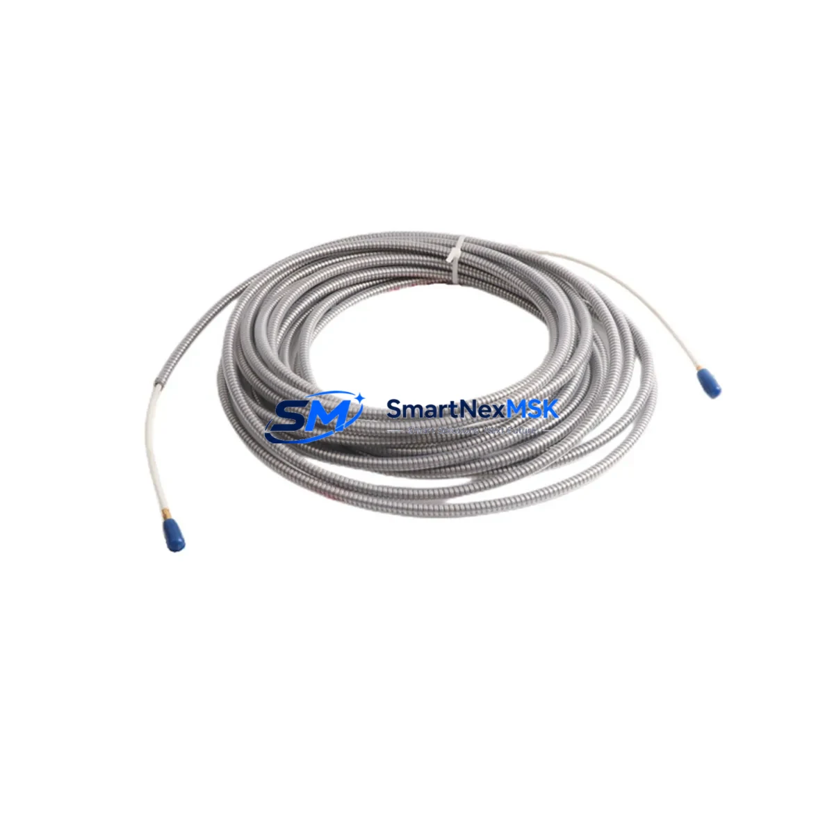
The Bently Nevada 18622-030-01 is a 30-foot (9-metre) proximity probe extension cable engineered for seamless integration into 3300 XL Series vibration monitoring systems. As legacy machinery protection platforms age and OEM spare parts become increasingly difficult to source, this extension cable serves as a direct, drop-in replacement that preserves signal integrity between the proximity probe tip and the proximitor monitor — without requiring rewiring, re-ranging, or software reconfiguration. Whether you are restoring a failed measurement loop, upgrading a control cabinet, or executing a planned outage retrofit, the 18622-030-01 is a field-proven solution trusted by reliability engineers and maintenance teams worldwide.
Designed to interface directly with the Bently Nevada 3300 XL 8mm Proximity Transducer System, this cable maintains the precise electrical characteristics — including capacitance, impedance, and shielding continuity — required for accurate eddy-current displacement measurement. The armoured, low-noise coaxial construction minimises electromagnetic interference in environments where variable-frequency drives, high-voltage bus bars, and motor control centres operate in close proximity to instrumentation wiring.
Upgrade Compatibility Table
| Parameter | Detail |
|---|---|
| SKU / Part Number | 18622-030-01 |
| Compatible Series | Bently Nevada 3300 XL (8 mm Proximity System) |
| Cable Length | 30 ft (9.14 m) |
| Connector Interface | Standard BNC / coaxial termination compatible with 3300 XL Proximitor |
| Signal Type | Eddy-current proximity, -24 VDC bias, 200 mV/mil sensitivity |
| Common Replacement For | 18622-030-01 (OEM), legacy 3300 series extension cables |
| Installation Requirement | No re-ranging required; verify probe gap (10–90 mil) after installation |
| Communication Compatibility | Passive signal cable; compatible with all 3300 XL monitor inputs |
| Retrofit Recommendation | Replace probe, extension cable, and proximitor as a matched set when possible |
| Commissioning Note | Confirm DC bias voltage at monitor input terminal after loop reassembly |
| Warranty | 12 Months from date of shipment |
Retrofit Planning for Existing Automation Systems
Replacing a proximity probe extension cable in an operating plant requires careful coordination across multiple system components. In a typical 3300 XL installation, the measurement loop consists of three matched elements: the proximity probe (such as the Bently Nevada 330101-00-06-10-02-00 or 330103 series tip), the extension cable (18622-030-01), and the proximitor module (such as the 3300 XL 8mm Proximitor, part 330180-X1-CN). All three must be electrically matched to maintain the calibrated sensitivity of 200 mV/mil. Substituting only the extension cable while retaining an aged or mismatched probe tip can introduce measurement drift that triggers nuisance trips on the 3500/22M Transient Data Interface or the 3500/42M Proximitor Monitor.
During cabinet-level upgrades, technicians frequently encounter situations where the existing cable routing passes through conduit shared with power wiring. In these cases, the shielded construction of the 18622-030-01 is critical. Ensure the cable shield is grounded at one end only — typically at the proximitor end — to prevent ground loops that can corrupt the -24 VDC bias signal. If the control cabinet also houses a 3500 Rack System with a 3500/20 Rack Interface Module, verify that the rack’s power supply module (3500/15 Power Supply) is delivering stable DC output before reconnecting the measurement loop, as voltage sag can cause false gap readings during startup.
For plants migrating from older 3300 Series (non-XL) installations to the current 3300 XL platform, the extension cable pinout and connector style may differ. In such cases, a junction box adapter or a full transducer system replacement — including the 3300 XL 8mm probe, the 18622-030-01 extension cable, and the corresponding proximitor — is the recommended upgrade path. This approach also simplifies future integration with System 1 Evolution condition monitoring software, which relies on consistent transducer sensitivity values stored in the 3500 rack configuration.
I/O expansion projects that add new measurement points to an existing 3500 rack should also account for the 3500/32 4-Channel Relay Module and the 3500/93 Tachometer Input Module when planning cable routing and terminal block assignments. Proper labelling of each extension cable run — including the associated channel number, machine tag, and measurement direction (X or Y) — reduces commissioning time and prevents wiring errors during future maintenance windows.
Downtime Control During System Migration
Minimising unplanned downtime during a proximity probe extension cable replacement begins with pre-outage preparation. Before the maintenance window opens, verify that the replacement 18622-030-01 cable has been bench-tested for continuity, shield integrity, and correct DC bias response when connected to a known-good proximitor. Having a pre-tested, matched transducer set — probe, cable, and proximitor — staged at the work site eliminates the most common cause of extended outages: discovering a defective replacement part after the original has already been removed.
During the outage, follow a structured sequence: first, document the existing probe gap measurement and DC bias voltage at the monitor terminal. Then remove the old extension cable, install the 18622-030-01, reconnect the probe and proximitor, and verify the DC bias voltage is within the acceptable window (typically -10 to -18 VDC for a correctly gapped 8mm system). Only after confirming the bias voltage should the monitor channel be re-enabled and the machine brought back online. This sequence protects the original program logic in the 3500 rack — no configuration changes are required, and the monitor’s alarm and trip setpoints remain intact throughout the cable swap.
For critical machinery where even a brief interruption is unacceptable, consider a hot-standby approach using a spare 3300 XL Proximitor pre-wired with the new 18622-030-01 cable. The spare assembly can be connected and verified on a bench power supply before the outage begins, then swapped in as a complete unit during the maintenance window, reducing the in-field connection time to minutes rather than hours.
Retrofit Support FAQ
Q1: Is the 18622-030-01 a direct replacement for the original Bently Nevada part?
Yes. The 18622-030-01 is manufactured to the same electrical and mechanical specification as the original OEM part. It is a direct, drop-in replacement for the 3300 XL 8mm Proximity Transducer System and requires no re-ranging or recalibration when used with a correctly gapped probe and a compatible proximitor.
Q2: Do I need to reconfigure the 3500 rack monitor after replacing the extension cable?
No rack reconfiguration is required for a like-for-like cable replacement. The 3500 rack stores transducer sensitivity and gap parameters in its non-volatile configuration memory. Provided the replacement cable is the same length and specification as the original, the existing configuration remains valid. Always verify DC bias voltage at the monitor input terminal after reassembly to confirm loop integrity before re-enabling the channel.
Q3: How do I verify the cable is correctly installed before restarting the machine?
After installation, measure the DC bias voltage at the proximitor output terminal (or at the monitor input). For a standard 8mm system with a correctly set probe gap, the bias should read between -10 VDC and -18 VDC. A reading outside this range indicates a wiring error, incorrect probe gap, or a mismatched component. Do not restart the machine until the bias voltage is confirmed within specification.
Q4: What warranty coverage is provided, and what does it include?
All 18622-030-01 extension cables supplied by SMARTNEXMSK carry a 12-month warranty from the date of shipment. The warranty covers manufacturing defects in materials and workmanship, including connector integrity, shield continuity, and cable insulation. Each unit undergoes outgoing quality inspection and functional testing prior to dispatch. For warranty claims or technical support, contact our team directly.
© 2026 SMARTNEXMSK. All rights reserved.
Original Source: https://smartnexmsk.com
Contact: sales@smartnexmsk.com | +86 18259474341


