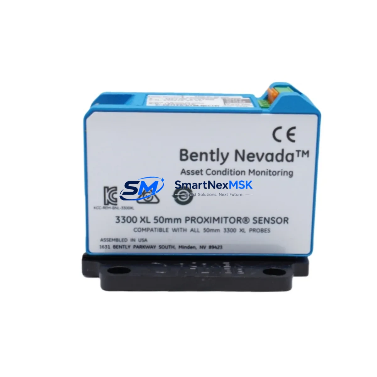
Bently Nevada 18745-04-05 Retrofit-Ready Proximitor Sensor for 3300 XL Control Systems
The Bently Nevada 18745-04-05 is a high-precision eddy-current Proximitor Sensor engineered for the 3300 XL Series vibration monitoring platform. As legacy machinery protection systems reach end-of-service life, this module serves as a verified drop-in replacement for discontinued or degraded sensors in rotating equipment protection applications — including turbines, compressors, pumps, and gearboxes operating under continuous monitoring requirements.
For facilities running aging 3300 XL racks, the 18745-04-05 provides a direct retrofit path without requiring changes to existing field wiring, terminal block assignments, or monitor configuration. The sensor outputs a standard -24 VDC bias voltage signal compatible with the full range of 3300 XL Series monitors, including the 3300/16 and 3300/20 proximity transducer monitors. Engineers replacing failed or out-of-tolerance sensors can install this unit and resume monitoring with minimal recalibration effort, provided the probe and extension cable assembly — typically a 330130 or 330180 series probe paired with a matching extension cable — remain within specification.
Upgrade Compatibility Table
| Parameter | Details |
|---|---|
| SKU / Part Number | 18745-04-05 |
| Series Compatibility | Bently Nevada 3300 XL Vibration Monitoring System |
| Signal Output | -24 VDC bias; standard eddy-current proximity output |
| Mounting / Installation | Direct replacement; no bracket modification required |
| Terminal Wiring | Compatible with existing 3300 XL terminal block layouts |
| Communication Protocol | Analog signal; integrates with 3300 XL monitor backplane |
| Replacement Recommendation | Replaces failed, drifted, or discontinued 18745-series sensors |
| Commissioning Notes | Verify gap voltage and scale factor post-installation; confirm with System 1 software |
| Warranty | 12 Months from date of shipment |
Retrofit Planning for Existing Automation Systems
Successful integration of the 18745-04-05 into an existing 3300 XL installation requires a structured pre-replacement assessment. Begin by auditing the current rack configuration: confirm the slot assignment of the affected proximity transducer monitor, verify that the 3300/16 or 3300/20 monitor card is functioning correctly, and document the existing gap voltage reading at the Proximitor output terminals. If the monitor card itself shows fault indicators, it may be necessary to address the 3300 XL monitor module before or alongside the sensor replacement.
Field wiring should be traced from the sensor back to the junction box and terminal block. In most 3300 XL installations, the Proximitor is connected via a two-conductor shielded cable routed through conduit to the machinery protection cabinet. Confirm that the extension cable — commonly a 330180-xx-xx series — is undamaged and within the specified length for the probe gap range. If the extension cable shows signs of insulation breakdown or connector corrosion, replace it concurrently with the 18745-04-05 to avoid introducing a new fault source after commissioning.
For facilities also upgrading their data acquisition layer, the 18745-04-05 integrates cleanly with the 3500 Series migration path. Sites transitioning from 3300 XL to the Bently Nevada 3500/42M or 3500/40M proximity monitor modules should note that the Proximitor sensor and probe assembly remain compatible across both platforms, reducing the hardware scope of the migration. The 3500 rack system uses a different backplane and I/O module architecture, so the 3500/01 rack power supply and 3500/20 rack interface module will need to be provisioned separately as part of any full platform upgrade.
Where the control system interfaces with a DCS or safety instrumented system, verify that the 4–20 mA or voltage output from the 3300 XL monitor is correctly mapped to the corresponding DCS input card. In Honeywell or Emerson DeltaV environments, this typically involves confirming the analog input channel scaling in the controller configuration. Any changes to the sensor or monitor hardware should be reflected in the SIS cause-and-effect matrix if the vibration channel feeds a safety function.
For sites using GE Mark V or Mark VI turbine control systems alongside Bently Nevada machinery protection, ensure that the vibration signal routing from the 3300 XL system to the Mark VI I/O pack is verified after sensor replacement. The VPRO or TPRO I/O modules in the Mark VI accept the standard Proximitor output, but signal scaling and trip setpoints should be confirmed in the ToolboxST configuration before returning the unit to service.
Downtime Control During System Migration
Minimizing unplanned downtime during a Proximitor sensor replacement requires preparation before the maintenance window opens. Prior to shutdown, retrieve the current System 1 vibration trend data for the affected measurement point and document the baseline gap voltage, direct vibration amplitude, and 1X/2X vector readings. This baseline serves as the acceptance criterion for post-installation verification.
During the replacement, keep the 3300 XL monitor in bypass mode if the plant safety system permits, to prevent a spurious trip on the unmonitored channel. After installing the 18745-04-05 and reconnecting the extension cable and probe, restore power to the Proximitor and measure the output voltage at the monitor terminal block. The gap voltage should fall within the linear range specified for the probe gap — typically between -10 VDC and -18 VDC for standard 5 mm probes. Adjust the probe gap mechanically if the reading is outside this range.
Once gap voltage is confirmed, remove the bypass and observe the vibration reading in System 1 or the local monitor display. Compare the live reading against the pre-shutdown baseline. If the 1X amplitude or phase angle deviates significantly, inspect the probe tip for contamination or mechanical damage before returning the machine to service. Document the completed replacement in the plant maintenance management system and update the sensor calibration record with the new installation date and gap voltage measurement.
For organizations managing multiple 3300 XL systems across a facility, maintaining a small buffer stock of 18745-04-05 sensors reduces the risk of extended downtime caused by procurement lead times. Given that this part number covers a widely deployed sensor configuration, availability from authorized distributors is generally reliable, but critical applications benefit from on-site spares held in a controlled storage environment.
Retrofit Support FAQ
Q: Is the 18745-04-05 a direct replacement for other 18745-series Proximitor sensors?
A: The 18745-04-05 is a specific configuration within the 18745 family, defined by its cable length and connector type. Before substituting another 18745-series variant, confirm that the cable length suffix and output characteristics match the original installation. Mismatched cable lengths will affect the gap voltage calibration range and may require probe gap readjustment.
Q: What commissioning steps are required after installation?
A: After physical installation, measure the Proximitor output voltage at the monitor terminal block to confirm the probe is within the linear gap range. Verify the reading in System 1 software or the local 3300 XL monitor display. Confirm that vibration amplitude and phase readings are consistent with pre-shutdown baseline data. Remove any monitor bypass and confirm that no fault or alert conditions are active before returning the machine to service.
Q: Can this sensor be used with a 3500 Series monitor rack?
A: Yes. The 18745-04-05 Proximitor is compatible with 3500 Series proximity monitor modules, including the 3500/42M. The sensor and probe assembly are platform-agnostic within the Bently Nevada eddy-current system architecture. However, the monitor module, rack power supply, and I/O configuration will differ between 3300 XL and 3500 Series installations and must be addressed separately.
Q: What warranty coverage is provided?
A: Each 18745-04-05 unit supplied by SMARTNEXMSK carries a 12-month warranty from the date of shipment. Units are functionally tested prior to dispatch. Warranty claims are supported by our technical team at sales@smartnexmsk.com. Replacement or repair is provided for units that exhibit failure under normal operating conditions within the warranty period.
© 2026 SMARTNEXMSK. All rights reserved.
Original Source: https://smartnexmsk.com
Contact: sales@smartnexmsk.com | +86 18259474341


