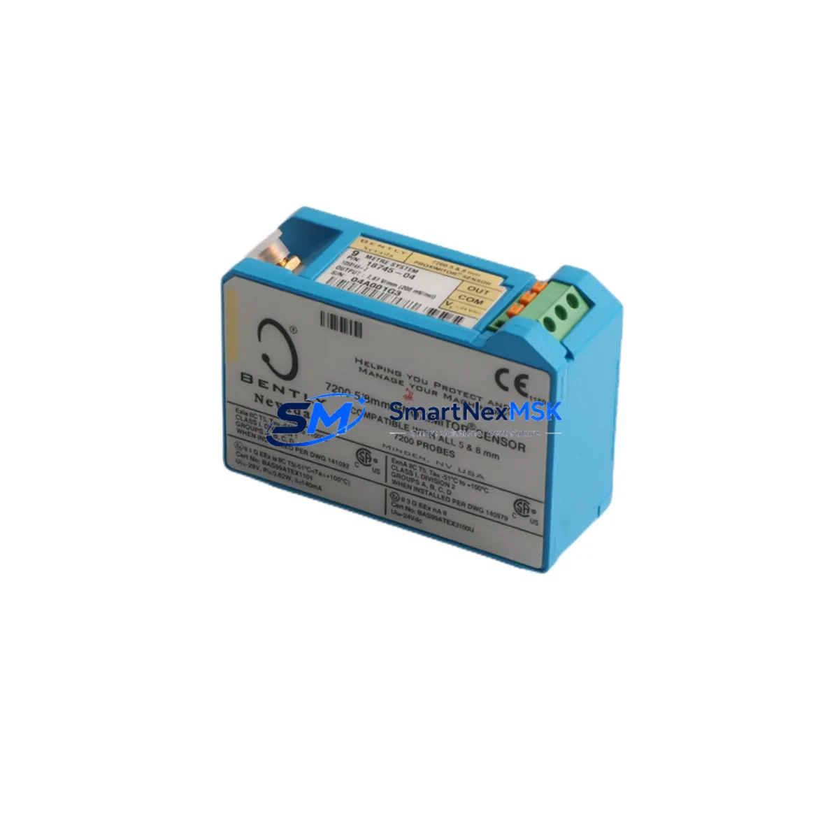
BENTLY NEVADA 18745-04 Retrofit-Ready Proximitor Sensor for 3300 XL Control Systems
The BENTLY NEVADA 18745-04 is a high-reliability eddy-current Proximitor Sensor engineered for seamless integration into 3300 XL Series machinery protection systems. As legacy vibration monitoring infrastructure reaches end-of-life, the 18745-04 serves as the preferred retrofit solution for facilities seeking to extend the operational life of their existing 3300 XL racks without committing to a full platform migration. Whether you are replacing a failed unit, upgrading a deteriorating sensor chain, or modernizing a control cabinet during a planned outage, the 18745-04 delivers the signal conditioning performance and dimensional compatibility required for a low-risk, high-confidence swap.
The 18745-04 outputs a standard -18 VDC proximitor signal compatible with the 3300 XL monitor cards, including the 3300/16 Dual Voting, 3300/20 Radial Vibration, and 3300/25 Thrust Position monitors. When replacing a failed sensor in a live rack, engineers must verify the gap voltage at the probe tip — typically between -10 VDC and -18 VDC at the nominal air gap — before returning the channel to service. The 3300 XL system’s OK relay logic depends on this voltage window, and an improperly gapped replacement will trigger a NOT OK condition even if the sensor itself is functional.
During retrofit planning, the 18745-04 is commonly deployed alongside the 3300/05-01-00-00 Power Supply module, which provides the regulated -24 VDC rail required by the Proximitor circuitry. If the existing power supply shows signs of output ripple or voltage sag — common failure modes in aging 3300 XL racks — it should be replaced concurrently to avoid nuisance trips after the sensor swap. The 3300/15-03-00-00 I/O module and associated terminal blocks should also be inspected for corrosion or loose terminations, as high-impedance connections at the BNC or MIL-C connector interface can introduce noise that mimics real vibration events.
Upgrade Compatibility Table
| Parameter | Detail |
|---|---|
| SKU / Part Number | 18745-04 |
| Brand | BENTLY NEVADA |
| Compatible Series | 3300 XL Machinery Protection System |
| Replaces / Supersedes | 18745-01, 18745-02, 18745-03 (earlier revisions) |
| Output Signal | -18 VDC (standard Proximitor output) |
| Supply Voltage | -24 VDC regulated |
| Connector Interface | MIL-C / BNC compatible with 3300 XL I/O modules |
| Installation Type | Direct drop-in replacement; no rack modification required |
| Communication Compatibility | Analog signal chain; compatible with 3300 XL monitor cards |
| Commissioning Requirement | Gap voltage verification at probe tip prior to channel enable |
| Warranty | 12 months from date of shipment |
Retrofit Planning for Existing Automation Systems
A successful 18745-04 retrofit begins well before the unit arrives on site. Maintenance engineers should pull the existing channel configuration from the 3300 XL System 1 software — or from the legacy Rack Configuration Utility if the site is running an older firmware baseline — and document the full-scale range, alert setpoints, danger setpoints, and OK limits for the affected channel. These parameters must be re-entered or verified after the sensor replacement, as some 3300 XL firmware versions reset channel defaults upon module re-initialization.
The physical installation requires attention to the extension cable routing. The 18745-04 is typically paired with a 330130 or 330180 series extension cable and a 330101 or 330103 series probe. If the existing extension cable shows insulation cracking, connector wear, or continuity anomalies, it should be replaced as part of the same work order. Running a new 18745-04 on a degraded extension cable is a common source of post-retrofit signal instability. The total system — probe, extension cable, and Proximitor — must be calibrated as a matched set to achieve the specified sensitivity of 200 mV/mil.
For sites integrating the 3300 XL rack into a DCS or SCADA environment via a 3500/92 Communication Gateway or a legacy 3300/93 Data Manager, the retrofit window is also an appropriate time to audit the communication link. Modbus RTU or RS-232 serial connections to the gateway should be tested for framing errors and response latency before the system is returned to automatic protection mode. If the site is planning a future migration to the 3500 Series platform, the 18745-04 retrofit provides an interim solution that preserves existing wiring infrastructure while the 3500/42M Proximitor Monitor and associated 3500 rack components are procured and staged.
Control cabinet work during the retrofit should include a thermal inspection of the 3300 XL rack backplane. Overheating at the backplane connector pins — often caused by years of vibration-induced micro-fretting — can cause intermittent channel faults that are misdiagnosed as sensor failures. Cleaning the backplane contacts and reseating all monitor cards before installing the 18745-04 eliminates this variable and reduces the risk of a repeat callout.
Downtime Control During System Migration
Minimizing unplanned downtime during a Proximitor sensor replacement requires a structured pre-outage checklist. Before isolating the channel, confirm that the machine train can be safely operated in a reduced-protection state or that a bypass jumper is authorized by the site’s safety management system. The 3300 XL system supports channel bypass via the front-panel keyswitch or through System 1 software, allowing the remaining channels to continue providing protection while the affected channel is serviced.
The original program logic — including setpoint values, time delays, and voting configurations stored in the 3300 XL monitor cards — is non-volatile and will be retained during a sensor swap that does not involve removing or cycling power to the monitor card itself. However, if the power supply module or the rack itself must be de-energized, a full configuration backup should be exported from System 1 before work begins. This backup serves as both a restoration reference and a compliance record for the site’s change management process.
Post-installation, the channel should be brought up in bypass mode and the gap voltage confirmed before the bypass is removed. A 30-minute observation period at normal operating speed, with the System 1 trend display active, is recommended to confirm that the 18745-04 is tracking shaft vibration cleanly and that no spurious OK-to-NOT-OK transitions occur. Only after this observation period should the channel be returned to full automatic protection and the work order closed.
Retrofit Support FAQ
Q1: Is the 18745-04 a direct replacement for earlier 18745 revisions?
Yes. The 18745-04 is backward compatible with the 18745-01, 18745-02, and 18745-03 within the 3300 XL system architecture. No rack modification or wiring change is required. Gap voltage must be re-verified after installation as probe-to-target gap may differ slightly between units due to manufacturing tolerances.
Q2: What commissioning steps are required after installation?
Verify supply voltage at the Proximitor input connector (-24 VDC ±1 VDC), confirm gap voltage at the probe tip is within the OK window specified on the monitor card faceplate, observe the channel output in System 1 for a minimum of 30 minutes at operating speed, and confirm that alert and danger setpoints are active and correctly configured before removing the channel bypass.
Q3: Can the 18745-04 be used with non-Bently Nevada probes or extension cables?
The 18745-04 is designed and calibrated for use with Bently Nevada 330101 and 330103 series probes and 330130 / 330180 series extension cables. Using third-party probes or cables will invalidate the 200 mV/mil sensitivity specification and may produce out-of-tolerance gap voltages. For retrofit applications, the complete probe-cable-Proximitor system should be replaced as a matched set whenever possible.
Q4: What does the 12-month warranty cover?
All 18745-04 units shipped by SMARTNEXMSK carry a 12-month warranty from the date of shipment, covering manufacturing defects and component failures under normal operating conditions. Each unit undergoes pre-shipment functional testing including output voltage verification and signal linearity check. Warranty claims are supported by our technical team at sales@smartnexmsk.com.
© 2026 SMARTNEXMSK. All rights reserved.
Original Source: https://smartnexmsk.com
Contact: sales@smartnexmsk.com | +86 18259474341


