Bently Nevada 190501-01-00-01 Retrofit-Ready Velocity Transducer for 3500 Series Control Systems
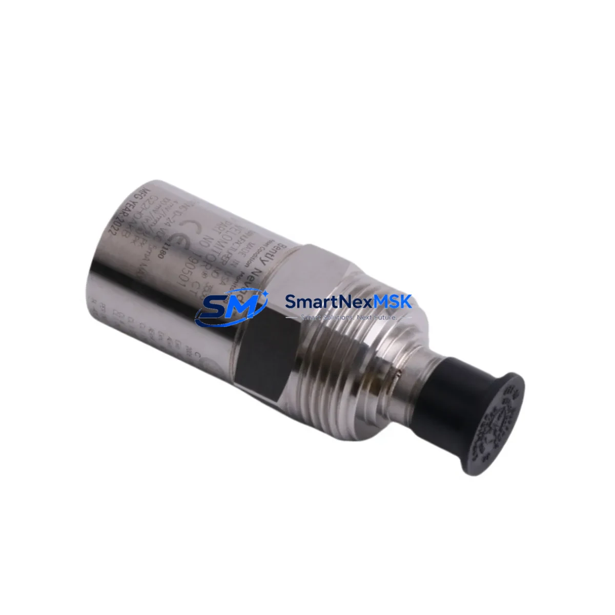
The Bently Nevada 190501-01-00-01 Velomitor CT is a high-performance piezoelectric velocity transducer engineered for continuous vibration monitoring in rotating machinery applications. Designed as a direct retrofit replacement within the Bently Nevada 3500 Series and 7200 Series condition monitoring platforms, this unit delivers a 4–20 mA output signal compatible with existing field wiring, terminal blocks, and monitor rack configurations. Whether you are replacing an end-of-life sensor on a critical compressor train, upgrading a legacy turbine protection system, or restoring a dormant monitoring loop, the 190501-01-00-01 provides a verified drop-in solution with minimal engineering intervention.
Industrial facilities operating aging machinery protection systems frequently encounter obsolescence challenges when original Bently Nevada sensors reach end-of-life or become unavailable through standard distribution channels. The 190501-01-00-01 addresses this gap directly, offering a stocked, tested, and warranty-backed alternative that preserves the integrity of existing 3500 Series rack infrastructure without requiring panel redesign or software reconfiguration.
Upgrade Compatibility Table
| Parameter | Details |
|---|---|
| SKU / Part Number | 190501-01-00-01 |
| Brand | Bently Nevada |
| Compatible Series | 3500 Series, 7200 Series Condition Monitoring |
| Output Signal | 4–20 mA (velocity proportional) |
| Mounting Interface | Standard Velomitor CT thread and connector pattern |
| Terminal Wiring | Compatible with existing field cable and terminal block layouts |
| Communication Compatibility | Analog loop; integrates with 3500/22M, 3500/42M, and 3500/45 monitor modules |
| Installation Requirement | No rack modification required; direct sensor swap |
| Commissioning Note | Verify full-scale range setting on associated monitor module after replacement |
| Replacement Recommendation | Suitable for direct substitution of discontinued Velomitor CT variants |
| Warranty | 12-Month Warranty — covers manufacturing defects and functional performance |
| Stock Status | In Stock — available for immediate shipment |
Retrofit Planning for Existing Automation Systems
Successful integration of the 190501-01-00-01 into an existing machinery protection system begins with a structured pre-replacement assessment. Engineers should first confirm the monitor module slot assignment within the 3500 Series rack — typically a 3500/22M Transient Data Interface or a 3500/42M Proximitor/Seismic Monitor — and verify that the channel configuration in System 1 software or the legacy Rack Configuration Software reflects the correct transducer type and sensitivity value. Mismatched sensitivity settings are the most common source of alarm threshold drift following a sensor swap.
Field wiring continuity should be confirmed at the junction box before disconnecting the original sensor. The Velomitor CT uses a two-wire 4–20 mA loop; technicians should document the existing loop resistance and supply voltage at the barrier or isolator to ensure the replacement unit operates within its specified current range. In installations where a Bently Nevada 3500/20 Power Supply module or a 3500/15 Power Supply feeds the sensor loop, verify that the available loop voltage remains within the 190501-01-00-01 operating window after accounting for cable resistance.
For facilities running parallel Keyphasor signals through a 3500/17 Keyphasor and Tachometer Module, confirm that the phase reference channel remains unaffected during the transducer swap. In multi-channel racks where the 190501-01-00-01 shares a backplane with 3500/40M Proximitor Monitor modules or 3500/50 Tachometer modules, the replacement procedure should be performed channel-by-channel to maintain continuous protection on adjacent measurement points.
Where the existing installation includes a Bently Nevada 3300 XL 8mm or 3300 XL 11mm proximity probe system on adjacent bearing positions, the retrofit plan should account for the different signal conditioning requirements between proximity and velocity channels. Technicians migrating from older 7200 Series racks to a 3500 Series platform should also review the I/O module mapping and update the System 1 database accordingly to reflect the new hardware addresses.
In control cabinet environments where the 190501-01-00-01 feeds into a DCS via a 4–20 mA analog input card — such as a Honeywell C300 controller I/O module or an Emerson DeltaV S-series analog input card — confirm that the engineering unit scaling in the DCS configuration matches the transducer’s velocity output range. HMI faceplate displays referencing the vibration trend should be reviewed to ensure alarm setpoints remain consistent with the new sensor’s calibration baseline. All configuration changes should be documented in the site’s Management of Change procedure before live commissioning.
Downtime Control During System Migration
Minimizing unplanned downtime during a Velomitor CT replacement requires a disciplined sequence of pre-work, execution, and verification steps. Before taking the measurement channel out of service, export the current rack configuration from the Bently Nevada Rack Configuration Software and archive the System 1 trend data for the affected measurement point. This baseline record protects the original alarm logic and allows rapid restoration if the replacement procedure encounters an unexpected issue.
During the physical swap, place the affected monitor channel in bypass mode through the 3500 Series rack front panel or via the System 1 operator interface to prevent spurious machinery trips. Confirm bypass status on the HMI before disconnecting field wiring. The 190501-01-00-01 is designed for direct connector compatibility, so mechanical installation time is typically under 30 minutes for a prepared technician with the correct torque specification and connector seating tool.
After reconnection, perform a loop check by injecting a known 4–20 mA signal at the field terminal and verifying the displayed engineering value at the monitor module and DCS HMI. Once signal integrity is confirmed, remove the bypass, observe the live vibration reading against the pre-replacement baseline, and document the as-found and as-left values in the site maintenance record. This structured approach consistently achieves channel restoration within a single planned maintenance window, protecting both production continuity and the integrity of the original control program logic.
Retrofit Support FAQ
Q1: Is the 190501-01-00-01 a direct replacement for the original Bently Nevada Velomitor CT, and will it work without modifying the 3500 Series rack?
Yes. The 190501-01-00-01 is a form-fit-function compatible replacement for the standard Velomitor CT. It uses the same thread pattern, connector type, and 4–20 mA output convention, allowing direct installation into existing sensor mounting positions without rack hardware changes. Only the sensitivity value in the monitor module configuration should be verified and adjusted if the replacement unit’s specification differs from the original.
Q2: What wiring checks are required before installing the replacement transducer?
Verify loop continuity, insulation resistance, and supply voltage at the field junction box before disconnecting the original sensor. Confirm that the loop resistance — including cable, barriers, and isolators — falls within the 190501-01-00-01 operating specification. Document terminal assignments and re-torque all connections to the manufacturer’s specification after installation.
Q3: How is compatibility with the existing System 1 software configuration verified after replacement?
After physical installation, perform a live signal check by comparing the displayed velocity reading in System 1 against a reference measurement from a calibrated handheld vibration meter on the same bearing housing. If the readings are within acceptable tolerance, the configuration is confirmed compatible. If a discrepancy exists, review the transducer sensitivity setting in the Rack Configuration Software and update accordingly.
Q4: What does the 12-month warranty cover, and what is the process for a warranty claim?
The 12-month warranty covers manufacturing defects and functional performance failures under normal operating conditions. Units that fail within the warranty period should be returned with a description of the fault condition and installation details. Replacement or repair will be arranged promptly. Contact sales@smartnexmsk.com or call +86 18259474341 to initiate a warranty claim.
© 2026 SMARTNEXMSK. All rights reserved.
Original Source: https://smartnexmsk.com
Contact: sales@smartnexmsk.com | +86 18259474341


