Bently Nevada 190501-02-00-04 Spare Velomitor CT 3500: Precision Spare for Rotating Machinery Protection
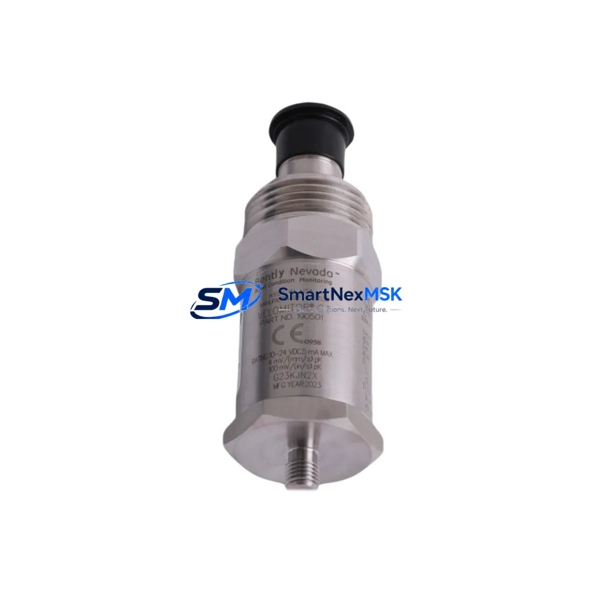
The Bently Nevada 190501-02-00-04 Velomitor CT is a piezoelectric velocity transducer engineered for continuous vibration monitoring on rotating machinery in critical industrial environments. As a maintenance-ready original spare, this unit is stocked and tested to support rapid field replacement, minimizing unplanned downtime in turbines, compressors, pumps, fans, and gearboxes protected by Bently Nevada 3500 Series machinery protection systems.
For maintenance engineers managing rotating equipment health, the 190501-02-00-04 is a cornerstone spare. Its broadband frequency response, rugged stainless-steel housing, and direct compatibility with the 3500/42M Velocity Monitor make it a reliable drop-in replacement for aging or failed transducers without requiring system reconfiguration. Each unit ships with full functional test documentation and is backed by a 12-month warranty from date of shipment.
Spare Maintenance Table
| Parameter | Specification |
|---|---|
| Part Number | 190501-02-00-04 |
| Brand | Bently Nevada |
| Series | 3500 / Velomitor CT |
| Product Type | Piezoelectric Velocity Transducer |
| Sensitivity | 100 mV/in/s (4 mV/mm/s) |
| Frequency Range | 2 to 1000 Hz (±3 dB) |
| Operating Temperature | -40°C to +121°C |
| Housing Material | 316L Stainless Steel |
| Connector Type | 2-pin MIL-C-5015 (integral cable option) |
| Compatible Monitor | Bently Nevada 3500/42M Velocity Monitor |
| Compatible System | Bently Nevada 3500 Series Machinery Protection |
| Mounting | 1/4-28 UNF threaded stud |
| Origin | USA |
| Warranty | 12 Months from shipment date |
| Condition | Original, new or reconditioned — tested before dispatch |
Maintenance Planning for Continuous Operation
When a Velomitor CT 190501-02-00-04 is flagged for replacement during a planned outage or emergency shutdown, experienced maintenance engineers know that the transducer itself is rarely the only component requiring attention. A thorough inspection of the surrounding measurement chain is essential to restore full system integrity and prevent repeat failures.
Start with the 3500/42M Velocity Monitor module seated in the 3500 rack — verify channel configuration, OK relay status, and alarm setpoints before reinstalling the new transducer. Inspect the 3500/20 Rack Interface Module (RIM) for communication faults and confirm the rack power supply, typically a 3500/15 Power Supply, is delivering stable ±24 VDC. A degraded power supply is a common root cause of transient velocity spikes that are misdiagnosed as transducer failure.
Check the interconnect cable assembly — Bently Nevada armored extension cables rated for the installation environment — for chafing, connector corrosion, or shield continuity breaks. Corroded MIL-spec connectors account for a significant proportion of false OK-relay trips in outdoor or high-humidity installations. While the cabinet is open, inspect nearby 3500/40M Proximitor Monitor channels and their associated proximity probes if the machine also uses eddy-current displacement monitoring; cross-contamination of vibration and position data can mask developing faults.
For systems integrated with a System 1 Evolution or System 1 Optimizer condition monitoring platform, confirm that the new transducer’s channel tag and engineering unit scaling are correctly mapped after replacement. Procurement engineers sourcing the 190501-02-00-04 should also consider holding a minimum of two units per critical machine train in the site spare-parts store, alongside a spare 3500/42M module and at least one set of replacement cable assemblies, to support both planned and emergency maintenance scenarios without waiting on lead times.
In older installations where the 3500 rack interfaces with a DCS via Modbus or FOUNDATION Fieldbus, verify that the communication module — such as a 3500/92 Communication Gateway — is correctly passing velocity data after the transducer swap. A missed configuration step here can result in the DCS displaying stale or zeroed velocity values, creating a false sense of machine health.
Site Replacement Workflow
Step 1 — Isolation & Permit: Obtain a Permit to Work. Isolate the 3500 rack channel for the affected transducer using the monitor’s bypass function to suppress alarms during maintenance without shutting down adjacent channels.
Step 2 — Transducer Removal: Disconnect the cable at the MIL-spec connector. Unscrew the 190501-02-00-04 from its mounting stud. Inspect the stud threads and mounting surface for corrosion or mechanical damage; replace the stud if necessary to ensure proper grounding and vibration coupling.
Step 3 — Installation of Replacement Unit: Thread the new 190501-02-00-04 to the specified torque. Reconnect the cable assembly, ensuring the connector is fully seated and the locking ring is engaged. Verify cable routing avoids heat sources and moving parts.
Step 4 — Functional Verification: Remove the bypass. Confirm the OK relay energizes and the velocity reading is within the expected baseline range for the machine at normal operating speed. Compare against historical trend data in System 1 or the DCS historian to validate the replacement.
Step 5 — Documentation: Record the replaced part number, serial number, installation date, and post-replacement readings in the CMMS. Update the site spare-parts inventory to trigger reorder of a replacement stock unit.
This workflow supports a typical replacement time of under 60 minutes for a prepared maintenance team, significantly reducing mean time to repair (MTTR) on critical rotating assets.
Spare Parts Support FAQ
Q1: Is the 190501-02-00-04 a direct replacement for older Velomitor CT variants?
Yes. The 190501-02-00-04 is the current catalog part number for the Velomitor CT and is backward-compatible with earlier suffix variants used in 3500 Series installations. No monitor reconfiguration is required for a like-for-like swap, though post-installation functional verification is always recommended.
Q2: What is included in the 12-month warranty?
Each unit is functionally tested prior to shipment. The 12-month warranty covers manufacturing defects and functional failure under normal operating conditions from the date of shipment. Units are dispatched with a test report. Warranty claims are supported by our technical team at sales@smartnexmsk.com.
Q3: How do you verify compatibility before shipment?
Our team cross-references the part number against the Bently Nevada 3500 Series compatibility matrix and confirms the unit’s sensitivity, connector type, and frequency range match the customer’s application. For non-standard installations, customers are encouraged to provide their monitor model and cable assembly details for pre-shipment verification.
Q4: What is your typical lead time and stock availability?
The 190501-02-00-04 is maintained as a stocked spare. Standard orders ship within 3–5 business days. For urgent shutdown recovery requirements, expedited dispatch is available — contact sales@smartnexmsk.com or call +86 18259474341 to confirm real-time availability.
© 2026 SMARTNEXMSK. All rights reserved.
Original Source: https://smartnexmsk.com
Contact: sales@smartnexmsk.com | +86 18259474341


