Bently Nevada 190501-04-00-04 Spare for Velomitor CT Automation: Spare Replacement & Industrial Downtime Risk Control
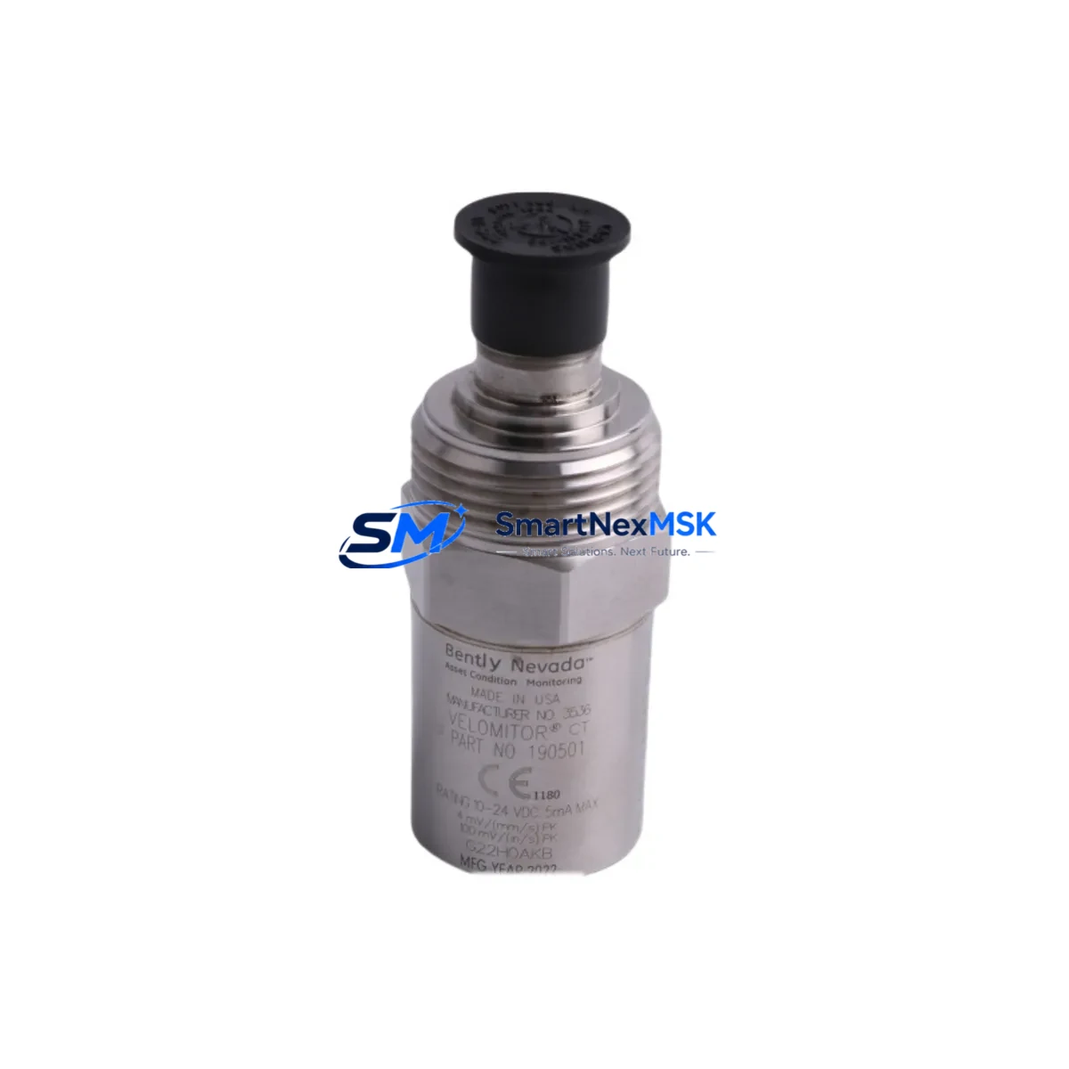
The Bently Nevada 190501-04-00-04 is an original Velomitor CT seismic velocity transducer engineered for continuous vibration monitoring on rotating machinery including turbines, compressors, pumps, and motors. As a maintenance-ready spare, this unit enables rapid field replacement to minimize unplanned downtime and restore machinery protection system integrity without extended lead times. Maintenance engineers and procurement teams managing critical rotating assets rely on stocked spares of this transducer to sustain 24/7 monitoring coverage across their Bently Nevada 3300, 3500, and System 1 platforms.
The 190501-04-00-04 outputs a velocity signal proportional to casing vibration, providing early warning of imbalance, misalignment, looseness, and bearing degradation. Its compact, hermetically sealed housing is rated for harsh industrial environments including high-temperature, high-humidity, and chemically aggressive atmospheres typical of petrochemical, power generation, and heavy manufacturing facilities. When this transducer is flagged during routine inspection or condition monitoring review, a pre-stocked replacement unit allows same-shift swap-out, keeping the machinery protection loop intact and avoiding costly production interruptions.
For procurement engineers, sourcing the 190501-04-00-04 as a certified original spare — rather than an uncertified substitute — ensures full compatibility with existing Bently Nevada monitor cards, junction boxes, and signal conditioning circuits. Each unit shipped by SMARTNEXMSK is tested prior to dispatch and covered by a 12-month warranty, providing documented traceability for maintenance records and audit compliance.
Spare Maintenance Table
| Parameter | Specification / Detail |
|---|---|
| Part Number / SKU | 190501-04-00-04 |
| Brand | Bently Nevada |
| Product Type | Seismic Velocity Transducer (Velomitor CT) |
| Compatible Series | Bently Nevada 3300, 3500, System 1 |
| Output Signal | Velocity (mV/mm/s or mV/in/s) |
| Measurement Type | Casing / Seismic Vibration |
| Frequency Range | Approx. 4.5 Hz – 2,000 Hz |
| Operating Temperature | -40°C to +121°C (typical industrial range) |
| Housing / Enclosure | Hermetically sealed, stainless steel |
| Connector Type | 2-pin MIL-spec connector (per variant suffix -04) |
| Cable Length | Per configuration (suffix -04-00-04) |
| Origin | USA |
| Application Environment | Petrochemical, Power Generation, Heavy Manufacturing, Offshore |
| Compatibility Confirmation | Verified against Bently Nevada 3300 and 3500 monitor card inputs |
| Maintenance Recommendation | Inspect mounting, cable integrity, and connector seating at each planned shutdown |
| Warranty | 12 Months from date of shipment |
| Pre-shipment Testing | Yes — functional output and continuity verified before dispatch |
Maintenance Planning for Continuous Operation
When replacing the 190501-04-00-04 Velomitor CT transducer during a planned or emergency shutdown, a thorough inspection of the surrounding measurement loop and control cabinet is essential to prevent repeat failures and ensure the machinery protection system is fully restored. Maintenance engineers should treat transducer replacement as an opportunity to audit the complete vibration monitoring chain.
Begin by inspecting the Velomitor CT extension cable (typically a Bently Nevada 330130 or equivalent armored cable) for chafing, connector corrosion, or shield continuity loss — cable degradation is a leading cause of false alarms and signal dropout that can be misdiagnosed as transducer failure. Next, verify the Bently Nevada 3300 or 3500 series monitor card input channel for correct bias voltage and signal conditioning settings; a faulty monitor card can damage a newly installed transducer within hours of restart.
Check the junction box terminal strips and barrier strips for loose terminations, moisture ingress, and corrosion — these are common failure points in outdoor or high-humidity installations. If the machinery protection system includes Bently Nevada 3500/42M or 3500/45 vibration monitor modules, confirm that the channel configuration matches the transducer sensitivity and measurement units before re-energizing. For systems using signal isolators or galvanic isolators between the transducer and the DCS or safety system, verify isolator output range and loop integrity.
In installations where the 190501-04-00-04 feeds into a Bently Nevada System 1 condition monitoring platform, update the asset configuration database to reflect the replacement date and confirm that alarm setpoints remain valid for the restored transducer. Where keyphasor probes (such as the Bently Nevada 330180 series) are installed on the same shaft, verify their gap voltage and signal quality simultaneously, as keyphasor signal integrity directly affects phase-referenced vibration analysis.
For facilities maintaining aging machinery protection systems, consider stocking companion spares including Bently Nevada 330400 series proximity probes, 3300 XL 8mm extension cables, and 3500/20 rack power supply modules to support rapid multi-point restoration during extended shutdowns. Procurement engineers should also maintain a minimum buffer stock of 3500 series I/O module spares and terminal board assemblies to avoid single-point-of-failure exposure across the monitoring rack.
Site Replacement Workflow
Step 1 — Isolation & Permit: Obtain a work permit and isolate the machinery protection channel at the monitor rack. Do not de-energize the full rack if other channels are active and protecting running equipment.
Step 2 — Transducer Removal: Disconnect the extension cable at the transducer connector. Remove the 190501-04-00-04 from its mounting pad, noting the orientation and torque applied to the mounting stud. Inspect the mounting surface for corrosion or damage.
Step 3 — Compatibility Verification: Confirm the replacement unit part number matches 190501-04-00-04 exactly, including suffix digits, which encode connector type, cable length, and housing configuration. Substituting an incorrect suffix variant can result in signal incompatibility or mechanical misfit.
Step 4 — Installation: Mount the replacement transducer to the specified torque. Reconnect the extension cable, ensuring the connector is fully seated and the locking ring is engaged. Inspect the cable routing for contact with hot surfaces or moving parts.
Step 5 — Loop Verification: Re-energize the monitor channel and verify bias voltage at the monitor card input is within the Bently Nevada specified range. Confirm the vibration reading is within expected baseline range for the machinery at rest or at operating speed.
Step 6 — Documentation: Record the replacement in the maintenance management system (CMMS) with the new unit serial number, installation date, and post-installation readings. Retain the warranty certificate for the 12-month coverage period.
This workflow is compatible with legacy Bently Nevada 3300 systems and current 3500 series racks, minimizing system reconfiguration and reducing total replacement time to under two hours for experienced maintenance teams.
Spare Parts Support FAQ
Q1: Is the 190501-04-00-04 a direct drop-in replacement for older Velomitor CT variants?
The 190501-04-00-04 is designed as a direct replacement within the Velomitor CT product family. The suffix digits (-04-00-04) define the connector type and cable configuration. Before installation, confirm that the suffix matches the original unit installed on your machinery. If the original unit carried a different suffix, consult the Bently Nevada compatibility matrix or contact SMARTNEXMSK for cross-reference support. No firmware or software reconfiguration is typically required when replacing like-for-like within the 3300 or 3500 monitor platform.
Q2: What pre-shipment testing is performed on each unit?
Every 190501-04-00-04 unit shipped by SMARTNEXMSK undergoes functional output verification and electrical continuity testing prior to dispatch. Test records are available upon request for facilities requiring documented incoming inspection evidence. Units are packaged in anti-static, shock-protected packaging to prevent transit damage.
Q3: How should this spare be stored in a maintenance inventory?
Store the 190501-04-00-04 in a dry, temperature-controlled environment away from strong magnetic fields and mechanical shock. Keep the unit in its original packaging until installation. Recommended storage temperature is 0°C to +60°C with relative humidity below 85% non-condensing. Inspect stored units annually for connector corrosion and seal integrity. The 12-month warranty period begins from the date of shipment, not the date of installation.
Q4: What is the lead time and long-term supply availability?
SMARTNEXMSK maintains stock of the 190501-04-00-04 to support urgent maintenance and planned procurement cycles. Standard orders are processed within 1–3 business days with express shipping options available for emergency downtime situations. For facilities managing aging Bently Nevada systems where OEM supply has been discontinued or lead times are extended, SMARTNEXMSK provides long-term spare parts support to extend system service life beyond OEM end-of-life dates.
© 2026 SMARTNEXMSK. All rights reserved.
Original Source: https://smartnexmsk.com
Contact: sales@smartnexmsk.com | +86 18259474341


