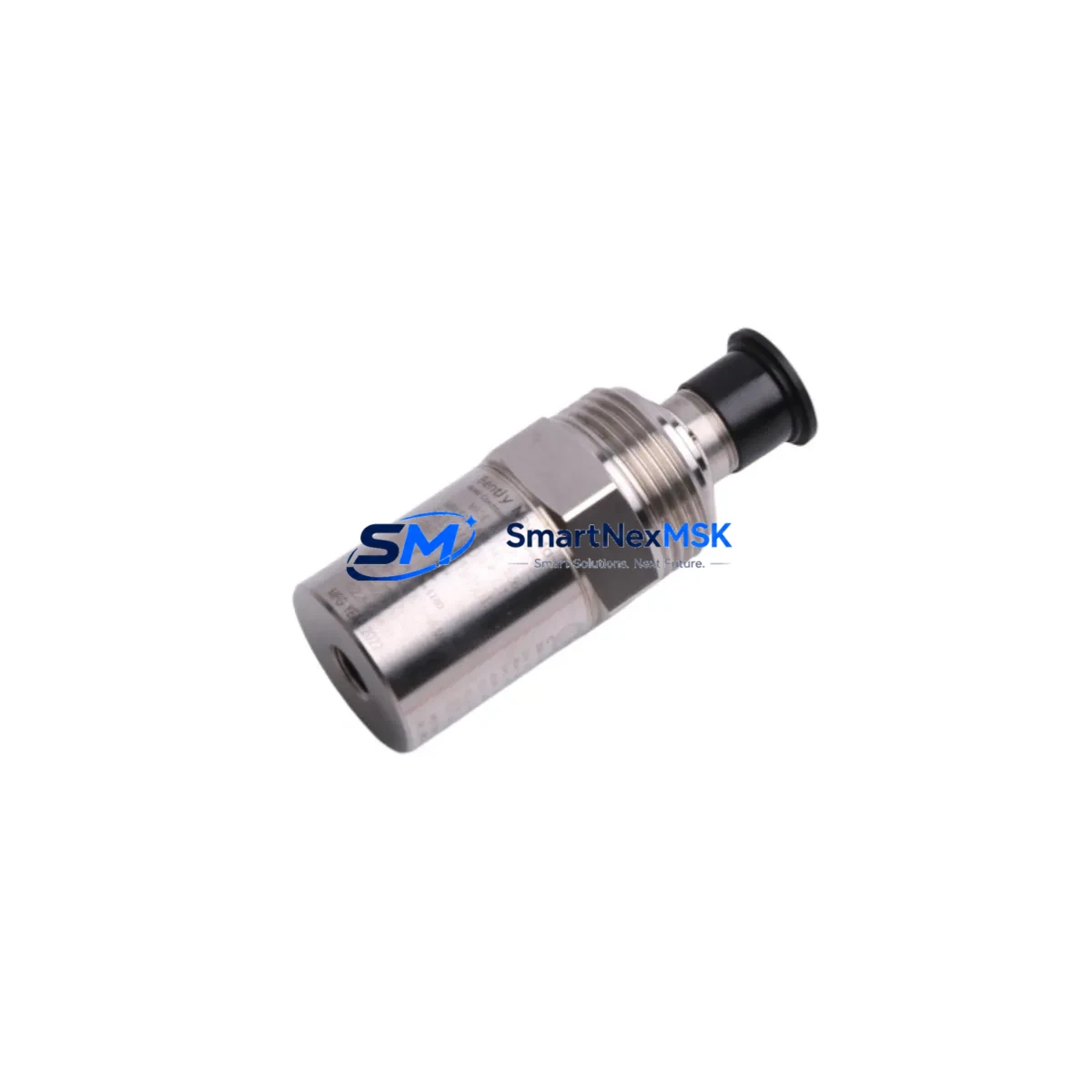
Bently Nevada 190501-04-00-CN Retrofit-Ready Seismic Velocity Transducer for 190501 Series Control Systems
The Bently Nevada 190501-04-00-CN is a seismic velocity transducer engineered for continuous vibration monitoring in rotating machinery protection systems. As a retrofit-ready replacement, this unit is fully compatible with existing 190501 Series monitor racks and Bently Nevada 3500 Series machinery protection systems, enabling plant engineers to execute drop-in upgrades without modifying field wiring, terminal blocks, or monitor configuration files. Whether you are replacing a failed unit on a critical compressor train, upgrading an aging turbine protection panel, or restoring a dormant production line, the 190501-04-00-CN delivers verified dimensional, electrical, and signal compatibility with the original factory specification.
Upgrade Compatibility Table
| Parameter | Detail |
|---|---|
| SKU / Part Number | 190501-04-00-CN |
| Series Compatibility | Bently Nevada 190501 Series; 3500 Series Machinery Protection System |
| Transducer Type | Seismic Velocity (Electrodynamic) |
| Mounting Interface | Standard 190501 Series housing; direct bolt-on replacement |
| Terminal / Wiring | Compatible with existing 2-wire field cable; no rewiring required |
| Signal Output | Velocity (mV/mm/s); matches original monitor input scaling |
| Communication Compatibility | Passive analog output; compatible with 3500/42M, 3500/45, and 3500/46M monitor modules |
| Installation Requirement | Verify torque spec on mounting stud; re-zero monitor channel after installation |
| Commissioning Note | Confirm alert/danger setpoints in 3500 Rack Configuration Software (RCS) after swap |
| Replacement Recommendation | Direct drop-in for discontinued 190501-04-00-CN; no firmware update required |
| Warranty | 12-Month Warranty — covers manufacturing defects and signal performance |
Retrofit Planning for Existing Automation Systems
Successful retrofit of the 190501-04-00-CN begins well before the maintenance window opens. Engineers should pull the existing rack drawing to confirm the monitor slot assignment — typically a 3500/42M Proximitor/Seismic Monitor or a 3500/45 Position Monitor — and verify that the channel is configured for velocity input rather than proximity or acceleration. The 3500 Series rack accepts the transducer signal through a dedicated I/O module terminal strip; confirm that the existing field cable pair is intact and that shield grounding follows Bently Nevada’s single-point grounding practice to avoid common-mode noise on the velocity channel.
For plants running a full 3500 Series rack, the retrofit scope often extends beyond the transducer itself. The 3500/20 Rack Interface Module manages communication between the rack and the plant DCS or safety system via Modbus RTU or Ethernet/IP; verify that the rack firmware version supports the protocol gateway in use. If the plant is migrating from a legacy System 1 condition monitoring platform to System 1 Evolution, the transducer channel configuration must be re-imported or manually re-entered in the new software environment. The 3500 Rack Configuration Software (RCS) stores all setpoint, scale factor, and full-scale range data — back up the existing RCS configuration file before any hardware swap.
Plants operating older Bently Nevada 7200 Series or 9000 Series monitor panels alongside a newer 3500 rack should pay particular attention to signal scaling differences. The 190501-04-00-CN outputs a velocity signal calibrated to the 190501 Series specification; if the signal is being fed into a third-party vibration relay or a legacy 1900/65 machinery protection monitor, confirm the input impedance and full-scale voltage range match before energizing the channel. In mixed-generation panels, a 3500/92 Communication Gateway Module or a 3500/22M Transient Data Interface may be present — these modules do not require reconfiguration when only the field transducer is replaced, but their status LEDs should be checked post-swap to confirm normal rack communication.
For I/O-intensive retrofit projects involving multiple transducer replacements across a turbine or compressor train, consider staging the work by machine section to limit the number of monitor channels taken offline simultaneously. Each 3500 rack slot can be individually bypassed using the rack’s built-in bypass function, allowing adjacent channels — such as a 3500/40M Proximitor Monitor covering radial vibration or a 3500/46M Hydro Monitor covering axial position — to remain in protection mode while the seismic channel is serviced. This approach is particularly important in facilities where the safety instrumented system (SIS) relies on the 3500 rack’s relay outputs for emergency shutdown logic.
Before closing the control cabinet, verify that the transducer cable is routed away from high-voltage conductors and that the connector is fully seated and locked. A bench-level signal check using a portable calibration shaker or a signal simulator connected to the monitor’s test input confirms that the replacement 190501-04-00-CN is producing the expected mV/mm/s output before the machine is returned to service. Document the as-found and as-left vibration readings, the RCS configuration backup filename, and the technician sign-off in the plant’s maintenance management system.
Downtime Control During System Migration
Minimizing unplanned downtime during a seismic transducer replacement requires a structured pre-outage checklist. Before the machine is taken offline, confirm that a tested spare 190501-04-00-CN is on hand, that the 3500 RCS configuration backup is current, and that the maintenance team has reviewed the terminal wiring diagram for the specific rack slot. The actual transducer swap — disconnect field cable, remove mounting stud, install replacement, reconnect cable — typically takes under 30 minutes for a trained technician. The dominant time risk is post-installation verification: if the monitor channel does not return to normal status immediately, the most common causes are an incorrect scale factor entry in RCS, a loose shield connection at the I/O module terminal strip, or a torque issue on the mounting stud causing mechanical resonance at the transducer body.
To protect original program logic during the migration, do not modify the 3500 rack configuration file unless a setpoint change has been formally approved through the plant’s management of change (MOC) process. The existing alert and danger setpoints, time delays, and relay voting logic should be preserved exactly as configured. If the plant’s DCS — whether a Honeywell Experion, Emerson DeltaV, or ABB 800xA system — receives vibration data from the 3500 rack via OPC or Modbus, confirm that the data tags are returning valid engineering-unit values after the transducer is reinstalled and the channel is taken out of bypass. A brief functional test at reduced machine speed before returning to full load provides additional confidence that the replacement transducer is performing within specification and that the protection system will respond correctly to an actual vibration event.
Retrofit Support FAQ
Q1: Is the 190501-04-00-CN a direct replacement for the original discontinued part?
Yes. The 190501-04-00-CN is a verified drop-in replacement for the original Bently Nevada 190501-04-00-CN seismic velocity transducer. Mechanical dimensions, mounting thread, connector pinout, and signal output scaling are identical to the factory original. No modifications to the monitor rack configuration, field wiring, or terminal block assignments are required.
Q2: What commissioning steps are required after installation?
After physical installation, remove the channel bypass in the 3500 Rack Configuration Software, confirm that the OK LED on the monitor module illuminates, and verify that the vibration reading is within the expected baseline range for the machine at rest or at operating speed. Check that alert and danger setpoints are active and that relay outputs are in the correct de-energized state. Record the as-left vibration amplitude and phase for trending purposes.
Q3: Can this transducer be used with non-Bently Nevada monitor systems?
The 190501-04-00-CN produces a standard passive velocity output compatible with most industrial vibration monitors that accept a seismic velocity input in the mV/mm/s range. However, full compatibility should be verified against the target monitor’s input impedance, full-scale range, and connector specification before installation. For use with third-party systems, consult the monitor manufacturer’s input specification sheet.
Q4: What does the 12-month warranty cover?
The 12-month warranty covers manufacturing defects, signal output accuracy within the published specification, and mechanical integrity of the transducer housing and connector. Warranty claims are processed upon return of the defective unit with a completed failure report. Units showing evidence of mechanical impact, improper installation torque, or exposure to fluids outside the rated environmental specification are evaluated on a case-by-case basis. Contact sales@smartnexmsk.com to initiate a warranty claim.
© 2026 SMARTNEXMSK. All rights reserved.
Original Source: https://smartnexmsk.com
Contact: sales@smartnexmsk.com | +86 18259474341


