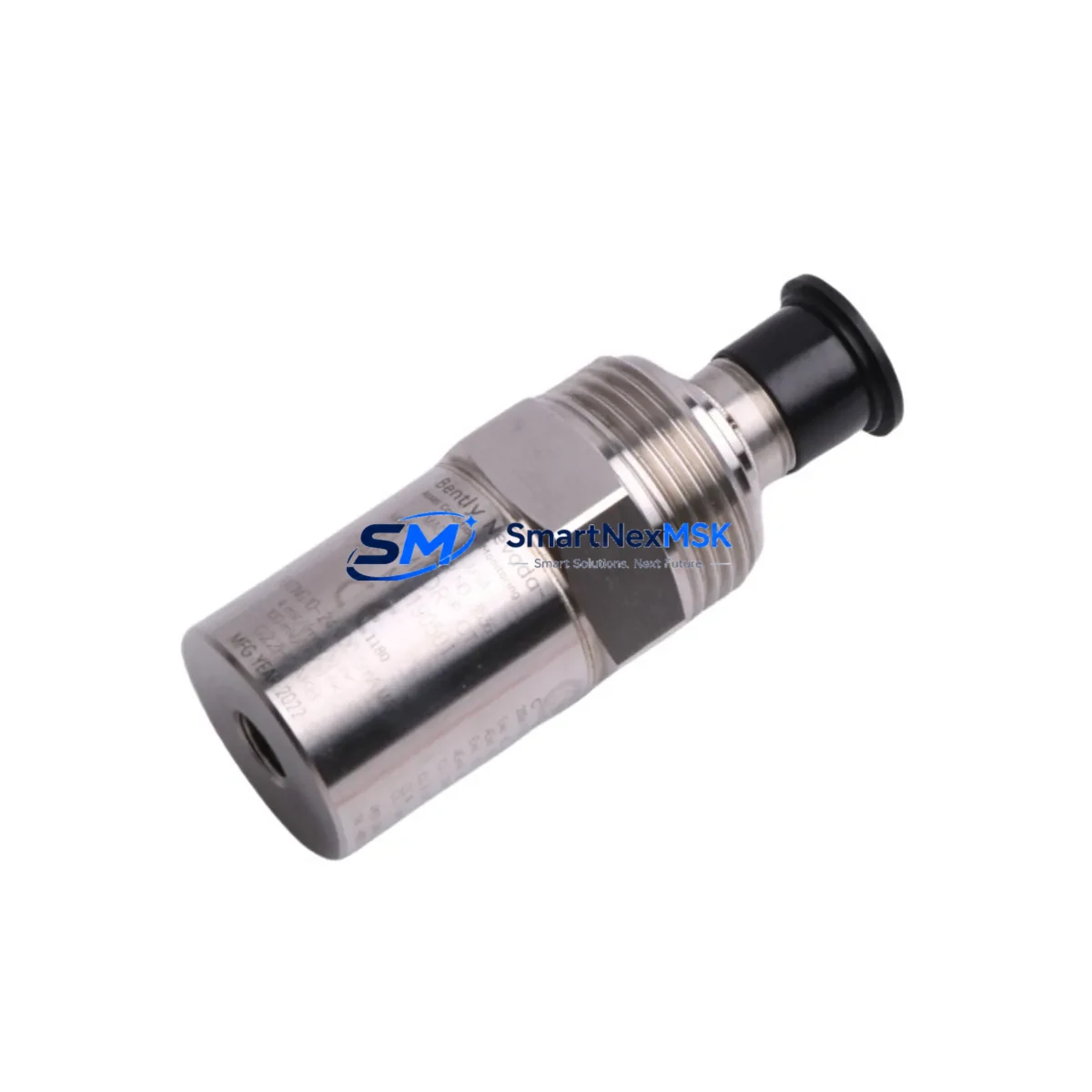
Bently Nevada 190501-05-00-04 Retrofit-Ready Velocity Transducer for Legacy Control Systems
The Bently Nevada 190501-05-00-04 Velomitor CT is a high-performance seismic velocity transducer engineered for continuous vibration monitoring in rotating machinery applications. As legacy condition monitoring systems age and original components reach end-of-life, the 190501-05-00-04 serves as a proven retrofit-ready replacement that integrates directly into existing Bently Nevada 3300 Series and 3500 Series monitoring racks without requiring hardware redesign or signal conditioning changes. Whether you are upgrading a turbine protection panel, replacing a failed transducer on a compressor train, or modernizing a legacy vibration monitoring cabinet, this unit delivers the measurement accuracy and mechanical compatibility your system demands.
Facilities running Bently Nevada 3300/05 or 3300/16 monitors will find the 190501-05-00-04 a direct functional replacement, maintaining the same 4–1000 Hz frequency response and velocity output signal that downstream monitors and DCS inputs expect. Engineers migrating from older Velomitor XA or standard Velomitor units to the Velomitor CT variant benefit from improved low-frequency response and enhanced EMI shielding — critical in environments where variable-frequency drives, large motors, and high-current bus bars generate significant electrical noise.
Upgrade Compatibility Table
| Parameter | Details |
|---|---|
| SKU / Part Number | 190501-05-00-04 |
| Brand / Manufacturer | Bently Nevada (Baker Hughes) |
| Series Compatibility | Bently Nevada 3300 Series, 3500 Series monitoring systems |
| Replaces / Supersedes | Velomitor XA (330500-00-00), standard Velomitor variants |
| Output Signal | Velocity (mV/mm/s or mV/in/s), compatible with existing monitor input cards |
| Frequency Response | 4–1000 Hz (±3 dB) |
| Mounting Interface | Standard Velomitor CT mounting thread; no adapter required for most installations |
| Communication / Protocol | Analog signal; compatible with 3300/05, 3300/16, 3500/42M, 3500/42E monitor cards |
| Installation Requirement | Verify cable connector type (2-pin MIL-C vs. integral cable); confirm cable length |
| Commissioning Notes | Re-enter transducer sensitivity in monitor configuration; verify alarm setpoints post-installation |
| Warranty | 12-Month Warranty — covers manufacturing defects and functional performance |
Retrofit Planning for Existing Automation Systems
A successful retrofit of the 190501-05-00-04 into an operating plant begins well before the transducer arrives on site. Start by auditing the existing wiring from the transducer junction box back to the monitor rack. Most 3300 Series installations use shielded twisted-pair cable terminated at a Bently Nevada 3300/05 Dual Velocity Monitor or a 3300/16 Dual Velocity Monitor input card. Confirm that the existing cable is rated for the signal frequency range and that shield grounding follows Bently Nevada’s single-point grounding practice — improper shield termination is one of the most common causes of elevated noise floors after a transducer swap.
For facilities running a 3500 Series rack, the relevant monitor card is typically the 3500/42M or 3500/42E Proximitor/Seismic Monitor. Before removing the old transducer, document the current configuration in the 3500 Rack Configuration Software, including channel mode, transducer type, full-scale range, and alarm setpoints. After installing the 190501-05-00-04, re-enter the transducer sensitivity value (typically 100 mV/in/s for Velomitor CT) and perform a static calibration check using a Bently Nevada CA-02 Calibration Adapter or equivalent signal source.
In modernization projects where the control architecture is being upgraded from a legacy DCS to a newer platform, the 190501-05-00-04 can continue to serve as the field sensing element while the signal is re-routed through a new Bently Nevada 3500/22M Transient Data Interface or a System 1 Evolution gateway. This approach preserves the existing transducer wiring infrastructure and avoids the cost and downtime of full field rewiring. The System 1 software platform can then aggregate vibration data from multiple 3500 racks, enabling centralized condition monitoring across the plant.
When planning I/O expansion or adding new measurement points to an existing rack, the 190501-05-00-04 pairs naturally with other rack components including the 3500/20 Rack Interface Module for Modbus or Ethernet/IP communication, the 3500/15 Power Supply Module, and the 3500/32 4-Channel Relay Module for alarm output wiring. Facilities that also monitor shaft displacement will often have Bently Nevada 3300 XL 8mm proximity probes and 3300 XL extension cables installed in adjacent rack slots — the 190501-05-00-04 complements these proximity-based measurements by adding seismic casing vibration data to the overall machinery health picture.
For older installations where the HMI displays vibration trends from a legacy Bently Nevada Data Manager 2000 or an early System 1 workstation, verify that the historian tag assignments and engineering unit scaling are updated to reflect the new transducer’s sensitivity. Failure to update HMI scaling is a common oversight that results in incorrect vibration readings being displayed and logged after a transducer replacement, potentially masking real machinery faults.
Downtime Control During System Migration
Minimizing production downtime during a transducer replacement requires a structured pre-outage preparation plan. Before the maintenance window opens, pre-stage the 190501-05-00-04 alongside all required consumables: replacement cable glands, anti-seize compound for the mounting threads, a calibrated torque wrench, and a laptop loaded with the 3500 Rack Configuration Software. If the monitor rack supports online configuration changes, prepare the updated configuration file in advance so it can be downloaded to the rack immediately after the transducer is connected — this eliminates configuration time from the critical path.
Where the process cannot tolerate a full shutdown, consider using a Bently Nevada 3500/22M or a portable data collector such as a CSI 2140 Machinery Health Analyzer to maintain continuous vibration surveillance on adjacent measurement points while the affected channel is taken offline. This approach ensures that the overall machinery protection system remains active and that any developing fault on a nearby bearing or seal is not missed during the replacement window.
After reconnecting the transducer and restoring monitor power, perform a live signal check by observing the raw velocity waveform on the 3500 Rack’s front-panel display or through System 1. Confirm that the signal is within the expected noise floor for the machine at rest, then bring the machine to operating speed and verify that vibration readings are stable and consistent with historical baseline data. Document the as-found and as-left readings in the plant’s maintenance management system before closing the work order. This record supports future reliability analysis and demonstrates due diligence for compliance audits.
Retrofit Support FAQ
Q1: Is the 190501-05-00-04 a direct drop-in replacement for the Velomitor XA (330500-00-00)?
In most installations, yes. Both units use the same mounting thread and produce a velocity output signal compatible with Bently Nevada 3300 and 3500 series monitor input cards. However, the Velomitor CT has a different connector configuration on some variants — confirm the cable connector type (integral cable vs. 2-pin MIL-C connector) before ordering to ensure a direct swap without field wiring modifications.
Q2: Do I need to reconfigure the monitor card after replacing the transducer?
Yes. After installing the 190501-05-00-04, you must verify and update the transducer sensitivity setting in the monitor configuration. The Velomitor CT sensitivity is typically 100 mV/in/s (or 3.937 mV/mm/s). Entering an incorrect sensitivity value will cause the monitor to display and alarm on incorrect engineering unit values. Use the 3500 Rack Configuration Software or the 3300 Series configuration tool to confirm all channel parameters before returning the machine to service.
Q3: What wiring checks should be performed before and after installation?
Before removal, measure the existing transducer’s bias voltage and compare it to the expected range (typically −8 to −12 VDC for Velomitor types). After installing the 190501-05-00-04, re-measure bias voltage to confirm the new unit is powered correctly and the cable is intact. Also verify shield continuity and insulation resistance between the signal conductors and shield to rule out cable damage introduced during the swap.
Q4: What does the 12-month warranty cover?
The 12-month warranty covers manufacturing defects and functional performance failures under normal operating conditions. Each unit is functionally tested prior to shipment. The warranty does not cover damage resulting from improper installation, overvoltage, mechanical impact, or operation outside the specified environmental ratings. For warranty claims or technical support, contact our team directly.
© 2026 SMARTNEXMSK. All rights reserved.
Original Source: https://smartnexmsk.com
Contact: sales@smartnexmsk.com | +86 18259474341


