Bently Nevada 190501-06-00-00 Retrofit-Ready Velocity Transducer for 3500 & 2300 Series Control Systems
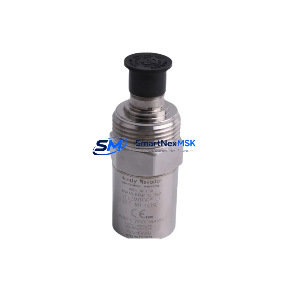
The Bently Nevada 190501-06-00-00 Velomitor CT is a piezoelectric velocity transducer engineered for direct drop-in replacement and retrofit integration within legacy Bently Nevada 3500 Series and 2300 Series continuous monitoring platforms. As original Velomitor CT units approach end-of-service life or become unavailable through standard distribution channels, the 190501-06-00-00 provides a wiring-compatible, mechanically equivalent, and signal-compatible upgrade path that minimizes engineering rework and eliminates the need for panel rewiring or monitor reconfiguration.
Designed for rotating machinery protection applications — including steam turbines, gas compressors, pumps, fans, and gearboxes — the 190501-06-00-00 delivers broadband velocity measurement with an integrated signal conditioning circuit, producing a low-impedance voltage output directly compatible with the 3500/42M Velocity Monitor and legacy 2300/25 Velocity Monitor input channels. The transducer’s integral cable and connector assembly matches the original Bently Nevada field wiring standard, allowing technicians to complete a swap without modifying terminal blocks, junction boxes, or existing cable runs.
Upgrade Compatibility Table
| Parameter | 190501-06-00-00 (This Unit) | Retrofit Notes |
|---|---|---|
| Compatible Monitor | 3500/42M, 2300/25, 2300/50 | No monitor reconfiguration required |
| Output Signal | Low-impedance voltage (ICP® compatible) | Matches original Velomitor CT output spec |
| Connector / Wiring | Integral cable, standard Bently Nevada termination | Direct terminal block reconnection; no rewiring |
| Mounting Interface | Standard stud mount (10-32 UNF or M6) | Verify existing mounting pad thread before installation |
| Frequency Range | 4.5 Hz – 1000 Hz (±3 dB) | Covers full machinery protection band |
| Communication / Protocol | Analog voltage — no fieldbus protocol | Integrates directly with 3500 rack backplane I/O |
| Replacement Path | Direct OEM-equivalent replacement | Replaces discontinued Velomitor CT variants |
| Commissioning Requirement | Zero-point calibration verification recommended | Use Bently Nevada Rack Configuration Software (RCS) |
| Warranty | 12-Month Warranty | Covers manufacturing defects and signal integrity |
Retrofit Planning for Existing Automation Systems
When planning a Velomitor CT replacement within an operating plant, the scope of work extends well beyond the transducer itself. A successful retrofit of the 190501-06-00-00 into a 3500 Series rack requires a structured review of the surrounding system architecture. Engineers should begin by auditing the 3500/42M Velocity Monitor channel assignments and confirming that the existing I/O module address mapping remains intact after the swap. In multi-channel racks, adjacent modules such as the 3500/40M Proximitor/Seismic Monitor or the 3500/22M Transient Data Interface should be checked for any shared power rail dependencies that could affect the replacement sequence.
Power supply capacity is a critical pre-installation checkpoint. The 3500/15 Power Supply Module or 3500/15E Enhanced Power Supply must be verified to have sufficient headroom to support the transducer’s bias current draw alongside all other active modules in the rack. In older installations where the 2300 Series rack is still in service, the 2300/25 Velocity Monitor’s internal power conditioning should be inspected before connecting the new 190501-06-00-00, as degraded internal regulators can introduce noise that masks genuine machinery faults.
Terminal block wiring should be documented with as-found photographs before disconnecting the old transducer. The 190501-06-00-00’s integral cable shield must be grounded at one end only — typically at the monitor end — to prevent ground loop interference. If the existing cable run passes through a junction box shared with proximity probe cables from a 3300 XL 8mm Proximity Transducer System, ensure that the shield grounding scheme is consistent across all channels to avoid common-mode noise injection into the velocity measurement chain.
For facilities running Bently Nevada System 1 condition monitoring software, the transducer channel configuration in the System 1 database should be updated to reflect the new unit’s sensitivity value (typically expressed in mV/mm/s or mV/in/s). This ensures that alarm setpoints, trend baselines, and spectral analysis thresholds remain calibrated to the physical measurement. If the plant also uses a 3500/92 Communication Gateway Module for Modbus or Ethernet/IP integration with a DCS or SCADA platform, no protocol reconfiguration is required — the gateway reads processed velocity values from the monitor, not raw transducer signals.
In applications where the 190501-06-00-00 is being installed as part of a broader control cabinet upgrade — for example, alongside a replacement 3500/20 Rack Interface Module or a new 3500/05 Rack Power Monitor — it is advisable to perform a full rack self-test using the Rack Configuration Software (RCS) after all modules are seated and wired. This confirms that all channel OK statuses are healthy and that no latent wiring faults were introduced during the retrofit work.
Downtime Control During System Migration
Minimizing unplanned downtime during a Velomitor CT replacement is achievable with disciplined pre-staging and a clear work sequence. Before the maintenance window opens, the replacement 190501-06-00-00 should be bench-tested using a portable signal simulator to confirm output sensitivity and frequency response. This eliminates the risk of installing a unit with a latent defect and discovering the fault only after the machinery is back online.
Where the 3500 rack supports hot-swap or bypass functionality — available on certain 3500/42M configurations — the affected channel can be placed in bypass mode to suppress spurious alarms during the transducer swap without triggering a full rack trip. This is particularly important in facilities where the 3500 rack is hardwired to a safety instrumented system (SIS) or emergency shutdown (ESD) logic solver, as an unintended channel fault signal could propagate to the shutdown circuit.
Original program logic stored in the 3500 rack’s non-volatile memory is not affected by a transducer replacement. Alarm setpoints, OK limits, and channel configuration parameters remain intact in the 3500/42M’s internal memory and in the RCS project file. Technicians should nonetheless export a current RCS configuration backup before beginning work, providing a restore point in the event that a rack power cycle is required during the installation. HMI screens connected via the 3500/92 gateway will continue to display the last valid process value during the bypass period, maintaining operator visibility of adjacent machinery channels throughout the swap.
Post-installation, a 30-minute observation period at normal operating speed is recommended to confirm that the new 190501-06-00-00 is producing a stable, noise-free velocity signal within the expected amplitude range for the machine’s baseline condition. Any deviation from the pre-replacement trend baseline should be investigated before returning the protection system to normal (non-bypass) operation.
Retrofit Support FAQ
Q: Is the 190501-06-00-00 a direct replacement for all Velomitor CT variants?
A: The 190501-06-00-00 is the standard 6-inch cable length Velomitor CT configuration and is a direct replacement for units with the same cable length suffix. Variants with different cable lengths (e.g., -12-00-00 or -25-00-00) use the same transducer body but differ in integral cable length. Confirm the cable length requirement against your existing field wiring run before ordering.
Q: Does replacing the transducer require recalibration of the 3500/42M monitor?
A: In most cases, no full recalibration is required if the replacement unit’s sensitivity specification matches the original. However, a zero-point verification and a channel OK check using RCS is strongly recommended after installation to confirm that the monitor is reading within expected limits. If the plant’s predictive maintenance program uses absolute vibration trending, a new baseline measurement should be recorded after the first full-speed run.
Q: Can the 190501-06-00-00 be used with a 2300 Series monitor instead of the 3500 rack?
A: Yes. The 190501-06-00-00 is signal-compatible with the 2300/25 and 2300/50 Velocity Monitor inputs. The low-impedance voltage output and bias current requirements of the Velomitor CT are within the input specifications of both 2300 Series monitor variants. No wiring adapters or signal conditioners are required.
Q: What does the 12-month warranty cover?
A: The 12-month warranty covers manufacturing defects, signal integrity failures, and connector assembly faults under normal operating conditions. Units that show evidence of mechanical damage from improper mounting, over-torquing of the stud mount, or exposure to temperatures or vibration levels outside the published operating envelope are not covered. All units are functionally tested prior to shipment to verify output sensitivity and frequency response within specification.
© 2026 SMARTNEXMSK. All rights reserved.
Original Source: https://smartnexmsk.com
Contact: sales@smartnexmsk.com | +86 18259474341


