Bently Nevada 190501-07-00-01 Spare for Velomitor CT Automation: Spare Replacement & Industrial Downtime Risk Control
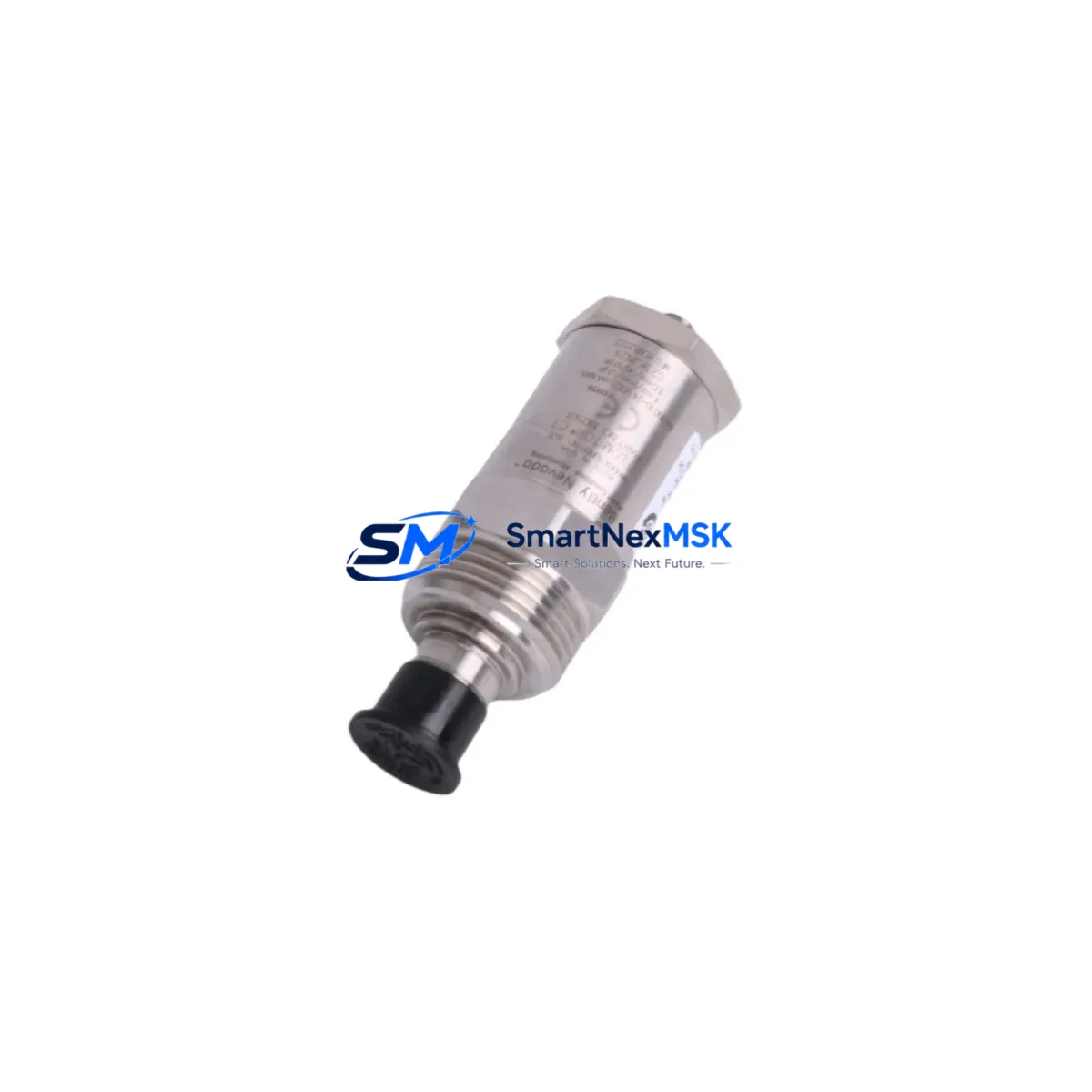
The Bently Nevada 190501-07-00-01 is a Velomitor CT piezoelectric velocity transducer engineered for continuous vibration monitoring in rotating machinery protection systems. As a maintenance-ready original spare, this unit is stocked and tested to support rapid field replacement, minimizing unplanned downtime in critical industrial environments including turbines, compressors, pumps, motors, and gearboxes. Whether you are executing a planned shutdown, responding to a trip alarm, or building a strategic spare parts inventory, the 190501-07-00-01 delivers the dimensional and electrical compatibility required for direct substitution in Bently Nevada Series 3500 and System 1 machinery protection architectures.
Maintenance engineers and procurement teams working with Bently Nevada platforms understand that velocity transducer failure — or degraded signal output — can trigger false trips or, worse, mask genuine machinery faults. Stocking the 190501-07-00-01 as a certified spare eliminates the lead-time risk associated with sourcing during an active fault condition. Each unit shipped from our inventory undergoes pre-shipment functional verification, and is backed by a 12-month warranty covering manufacturing defects and electrical performance.
Spare Maintenance Table
| Parameter | Specification |
|---|---|
| Part Number | 190501-07-00-01 |
| Brand | Bently Nevada |
| Series | Velomitor CT (190501 Series) |
| Type | Piezoelectric Velocity Transducer |
| Output Signal | Velocity (mV/mm/s or mV/in/s) |
| Frequency Range | Approx. 2 Hz – 1,000 Hz |
| Operating Temperature | -40°C to +121°C |
| Connector Type | 2-pin MIL-C-5015 style |
| Mounting | 1/4-28 UNF threaded stud |
| Housing Material | Stainless steel, IP67-rated |
| Compatibility | Bently Nevada 3500 Series, System 1, 3300 Series monitors |
| Application | Turbines, compressors, pumps, motors, gearboxes |
| Origin | USA |
| Condition | Original spare, new or refurbished-to-spec |
| Pre-shipment Test | Yes — functional verification included |
| Warranty | 12 months from date of shipment |
Maintenance Planning for Continuous Operation
When replacing the 190501-07-00-01 Velomitor CT transducer during a scheduled or emergency maintenance event, a thorough inspection of the surrounding measurement loop is essential to ensure signal integrity and system reliability. Maintenance engineers should begin by verifying the condition of the Bently Nevada 330130 or 330180 series extension cables connecting the transducer to the monitor rack — cable insulation degradation or connector corrosion is a common source of signal noise that can be misattributed to transducer failure.
At the monitor rack level, inspect the corresponding 3500/42M or 3500/45 velocity monitor module for any alarm or trip relay latching that may have been triggered by the fault event. If the monitor card shows signs of input channel saturation or relay contact wear, it should be replaced concurrently to avoid repeat trips after the transducer swap. The 3500/20 rack power supply module should also be checked for output voltage stability — an under-voltage condition can cause erratic transducer readings across all channels in the rack.
For installations where the Velomitor CT feeds into a System 1 condition monitoring platform, confirm that the I/O module mapping and channel configuration remain intact after replacement. If the system uses a 3500/92 communication gateway or Ethernet I/O module for data export to the DCS or historian, verify that the channel tag assignment is correctly restored following the transducer swap. In older installations, the 3500/15 power supply or 3500/05 system monitor module may require a rack reset to re-establish communication after a hot-swap event.
Procurement engineers building a spare parts kit for a Bently Nevada-equipped machinery train should consider stocking the following alongside the 190501-07-00-01: a set of 330130-series armored extension cables in the appropriate lengths for each measurement point, at least one spare 3500/42M velocity monitor card, a 3500/20 power supply module, and a selection of 3500 rack terminal blocks and I/O wiring harnesses. For sites with multiple measurement points, maintaining two to three Velomitor CT transducers in inventory is a recognized best practice under IEC 61511 functional safety guidelines for rotating machinery protection.
Site Replacement Workflow
Replacing the 190501-07-00-01 in the field follows a straightforward procedure that can be completed within a standard maintenance window. Begin by isolating the measurement channel at the 3500 monitor rack — place the affected channel in bypass mode to prevent a spurious trip during the transducer swap. Disconnect the extension cable at the transducer body, noting the cable routing and any strain relief clamps for reinstallation reference.
Remove the existing transducer by unscrewing the 1/4-28 UNF stud mount, taking care not to damage the mounting pad surface. Install the replacement 190501-07-00-01 to the manufacturer’s specified torque value — typically 2.3 N·m (20 in-lb) — and reconnect the extension cable, ensuring the connector is fully seated and the locking ring is engaged. Restore the channel from bypass mode and verify the live velocity reading against the baseline trend data in System 1 or the local monitor display. A reading within ±5% of the historical baseline confirms a successful replacement.
This direct-swap compatibility means no firmware changes, no recalibration of the monitor card, and no modification to the DCS tag configuration — significantly reducing the skill level required for field replacement and shortening the overall maintenance window. For legacy installations previously using the 190501-01-00-01 or 190501-03-00-01 variants, the 190501-07-00-01 provides an updated connector and cable interface while maintaining full electrical and mechanical compatibility with the existing monitor infrastructure.
Spare Parts Support FAQ
Q1: Is the 190501-07-00-01 a direct replacement for earlier Velomitor CT variants such as 190501-01-00-01?
Yes. The 190501-07-00-01 is electrically and mechanically compatible with earlier Velomitor CT variants in the 190501 series. The primary differences are in the connector interface and cable termination style. Confirm the extension cable part number before ordering to ensure connector compatibility, or order a matched cable set alongside the transducer.
Q2: What pre-shipment testing is performed on each unit?
Each 190501-07-00-01 unit undergoes functional verification prior to shipment, including output sensitivity check, insulation resistance test, and connector integrity inspection. A test report is available upon request. All units are shipped in anti-static packaging with protective end caps to prevent transit damage.
Q3: How should the 190501-07-00-01 be stored as a long-term spare?
Store in a dry, temperature-controlled environment between -20°C and +60°C, away from strong magnetic fields and vibration sources. The piezoelectric sensing element is stable in long-term storage; however, connector contacts should be inspected and cleaned annually if the unit remains unused for more than 12 months. Shelf life under proper storage conditions exceeds five years.
Q4: What is covered under the 12-month warranty?
The 12-month warranty covers manufacturing defects, electrical performance outside published specifications, and connector or housing integrity failures under normal operating conditions. Warranty claims are supported by our technical team at sales@smartnexmsk.com. Units damaged by incorrect installation torque, cable over-tension, or exposure to conditions outside the rated operating range are not covered under warranty.
© 2026 SMARTNEXMSK. All rights reserved.
Original Source: https://smartnexmsk.com
Contact: sales@smartnexmsk.com | +86 18259474341


