Bently Nevada 190501-09-00-04 Retrofit-Ready Velomitor CT for 3300/3500 Control Systems
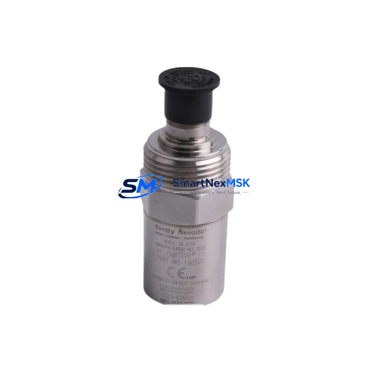
The Bently Nevada 190501-09-00-04 Velomitor CT is a high-performance piezoelectric velocity transducer engineered for continuous vibration monitoring on rotating machinery. As legacy Bently Nevada 3300 Series and 3500 Series monitoring systems reach end-of-life or require component-level replacement, the 190501-09-00-04 serves as a verified drop-in retrofit solution — preserving existing wiring infrastructure, signal conditioning chains, and machinery protection logic without requiring a full system overhaul.
Industrial facilities operating gas turbines, steam turbines, centrifugal compressors, and large electric motors rely on the Velomitor CT platform for its wide frequency response, robust stainless-steel housing, and compatibility with Bently Nevada’s 3300 XL 11 mm Proximity Transducer System and 3500/42M Proximitor/Seismic Monitor modules. When the original sensor reaches its service life or is discontinued from the OEM supply chain, sourcing a functionally equivalent replacement with documented compatibility is critical to maintaining API 670 machinery protection compliance.
Upgrade Compatibility Table
| Parameter | 190501-09-00-04 Specification | Retrofit Notes |
|---|---|---|
| Sensor Type | Piezoelectric Velocity (Velomitor CT) | Direct replacement for Velomitor XA and standard Velomitor variants |
| Output Signal | 4–20 mA (current loop, 2-wire) | Compatible with existing 3500/42M and 3300 XL monitor input cards |
| Frequency Range | 2–1000 Hz (±3 dB) | Covers standard rotating machinery vibration spectrum; no filter reconfiguration required |
| Supply Voltage | 18–30 VDC | Verify existing power supply capacity; 3500 rack power modules typically supply 24 VDC |
| Connector / Termination | 2-pin MIL-C-5015 or equivalent | Confirm field cable connector type before installation; adapter cables available |
| Mounting Thread | 1/4–28 UNF or M8 (specify at order) | Match to existing mounting boss on machinery casing |
| Housing Material | 316 Stainless Steel | Suitable for high-temperature and corrosive environments |
| Compatible Monitor Modules | 3500/42M, 3300 XL, 3500/25 | No firmware update required for standard channel configuration |
| Replacement Scope | Discontinued OEM part, aftermarket equivalent | Functionally equivalent; full bench test and calibration certificate included |
| Warranty | 12-Month Warranty | Covers manufacturing defects; includes pre-shipment functional verification |
Retrofit Planning for Existing Automation Systems
Successful integration of the 190501-09-00-04 into an existing Bently Nevada machinery protection system requires a structured pre-installation review. Before removing the legacy sensor, engineers should document the current channel configuration within the 3500 rack — specifically the 3500/42M Proximitor/Seismic Monitor card settings, including full-scale range, alert and danger setpoints, and time-delay parameters stored in the rack’s non-volatile memory. These settings are preserved in the rack and do not need to be re-entered after a sensor swap, but they must be verified against the new sensor’s sensitivity specification (typically 100 mV/g or 4 mA/in/s depending on output type).
The 3500 rack’s 3500/20 Rack Interface Module (RIM) manages communication between the monitoring system and the plant DCS or safety system via Modbus RTU, Modbus TCP, or Ethernet/IP. When replacing a sensor in a live system, it is advisable to place the affected channel in bypass mode through the 3500/20 RIM configuration software before disconnecting field wiring, preventing spurious alarms from propagating to the control room or triggering an emergency shutdown sequence.
Field wiring should be inspected at the junction box and at the 3500 rack’s I/O terminal block. The 190501-09-00-04 uses a shielded, twisted-pair cable run — typically Belden 9501 or equivalent — with the shield grounded at the rack end only to prevent ground loops. If the existing cable run exceeds 300 meters, verify that the loop resistance remains within the monitor card’s input impedance specification. In installations where the original cable was routed through conduit shared with high-voltage power wiring, consider re-routing or adding additional shielding to protect the low-level 4–20 mA signal from electromagnetic interference.
For facilities that also operate Bently Nevada 3300 XL 11 mm Proximity Transducer Systems on adjacent machinery trains, the retrofit process is similar but requires attention to the Proximitor sensor gap voltage, which is set independently of the Velomitor CT channel. If the control cabinet houses both proximity and velocity monitoring channels on a shared 3500/25 Keyphasor Module, confirm that the Keyphasor signal source remains undisturbed during the Velomitor replacement. The 3500/15 Power Supply Module within the rack should also be checked for available current headroom, particularly in fully populated racks where multiple 3500/42M cards are installed.
In plants transitioning from legacy 3300 Series racks to the current 3500 Series platform, the 190501-09-00-04 is compatible with both generations, making it a practical interim solution during phased migration. During such migrations, the 3500/92 Communication Gateway Module is often deployed to bridge legacy serial communication links to modern Ethernet-based plant networks, and the Velomitor CT’s analog output integrates cleanly into this architecture without requiring signal conversion hardware.
All units are pre-shipment tested against calibration standards traceable to NIST, and each unit ships with a calibration certificate and functional test report. In-stock inventory is maintained to support urgent replacement requirements, with standard lead times of 3–7 business days for international shipments.
Downtime Control During System Migration
Minimizing unplanned downtime during a Velomitor CT replacement is achievable with disciplined pre-work. The recommended approach is a hot-swap procedure executed during a scheduled maintenance window: place the affected 3500/42M channel in bypass via the rack configuration software, disconnect the field cable at the junction box (not at the sensor body), install the 190501-09-00-04 in the mounting boss, reconnect the field cable, verify the loop current reads within the expected idle range (typically 4 mA at zero velocity), then remove the channel bypass and confirm the monitor returns to normal operation status.
Original program logic stored in the plant DCS — including PID loops, interlock sequences, and HMI faceplate configurations referencing the vibration channel tag — is unaffected by the sensor replacement, provided the new sensor’s output scaling matches the original. If the HMI displays a raw engineering unit value derived from the 4–20 mA signal, verify the scaling factor in the DCS I/O configuration matches the new sensor’s sensitivity. In most cases, no DCS program modification is required.
For facilities using a Bently Nevada System 1 condition monitoring software platform, the historian tag associated with the replaced channel will continue to log data without interruption once the channel returns to active status. No tag remapping or database modification is necessary. This continuity of data logging is particularly valuable for facilities subject to API 670 compliance audits, where a complete vibration history record is required.
Where a parallel redundant monitoring channel exists — common in critical machinery protection applications — the redundant channel can remain active during the replacement, ensuring continuous machinery protection throughout the procedure. This approach eliminates the need for a full machinery shutdown in most non-SIL-rated applications, reducing the replacement window to under two hours for experienced field technicians.
Retrofit Support FAQ
Q: Is the 190501-09-00-04 a direct drop-in replacement for the original Bently Nevada Velomitor CT?
A: Yes. The 190501-09-00-04 is dimensionally and electrically equivalent to the original Bently Nevada Velomitor CT. It uses the same 2-wire 4–20 mA output, the same mounting thread, and the same connector interface. No modifications to the existing cable, junction box, or monitor rack configuration are required in standard installations.
Q: What pre-shipment testing is performed on each unit?
A: Every unit undergoes a full functional test including output linearity verification across the rated frequency range, insulation resistance check, and connector integrity inspection. A calibration certificate traceable to NIST standards is included with each shipment. Units are covered by a 12-month warranty against manufacturing defects from the date of shipment.
Q: How do I verify wiring compatibility before installation?
A: Confirm the field cable is a shielded twisted pair rated for the installation environment, that the shield is grounded at the rack end only, and that the total loop resistance (cable + termination) is within the 3500/42M input specification. Measure the supply voltage at the sensor connector with the cable connected but the sensor disconnected — it should read between 18 and 30 VDC. If the voltage is outside this range, inspect the 3500/15 Power Supply Module output and the cable for excessive resistance.
Q: Can this sensor be used in a 3300 Series rack as well as a 3500 Series rack?
A: Yes. The 190501-09-00-04 is compatible with both the Bently Nevada 3300 XL monitoring system and the 3500 Series platform. For 3300 Series installations, verify the monitor card’s input configuration matches the sensor’s output type (current loop vs. voltage output). Contact our technical team with your rack model and card part number for a configuration-specific compatibility confirmation before ordering.
© 2026 SMARTNEXMSK. All rights reserved.
Original Source: https://smartnexmsk.com
Contact: sales@smartnexmsk.com | +86 18259474341


