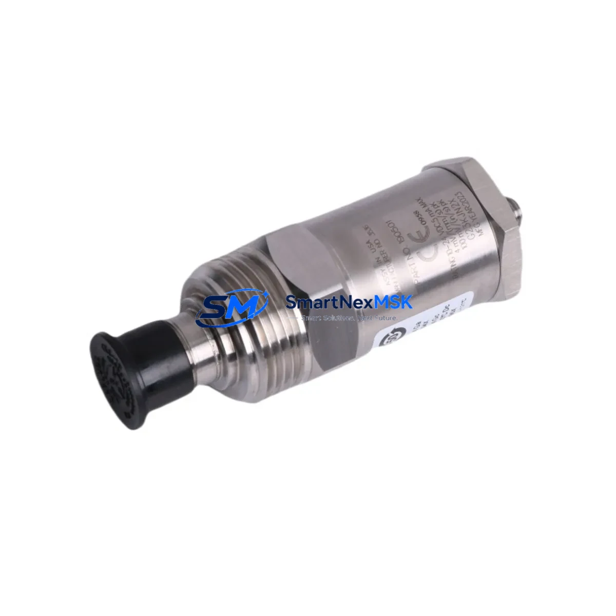
Bently Nevada 190501-11-99-01 Retrofit-Ready Velocity Transducer for 3500 Series Control Systems
The Bently Nevada 190501-11-99-01 is a Velomitor CT piezo-velocity transducer engineered for continuous vibration monitoring in rotating machinery applications. As legacy installations running older Bently Nevada 7200 Series and 3300 Series proximity systems approach end-of-life, the 190501-11-99-01 provides a validated, drop-in compatible upgrade path into the Bently Nevada 3500 Series machinery protection platform — one of the most widely deployed condition monitoring architectures in oil & gas, power generation, and petrochemical industries.
Whether you are replacing a failed unit on a critical compressor train, modernizing a turbine control cabinet, or executing a planned outage upgrade, the 190501-11-99-01 is stocked, tested, and ready to ship with a 12-month warranty covering both parts and workmanship.
Upgrade Compatibility Table
| Parameter | Details |
|---|---|
| Part Number | 190501-11-99-01 |
| Brand / OEM | Bently Nevada (Baker Hughes) |
| Series Compatibility | 3500 Series Machinery Protection System |
| Replaces / Upgrades | Older Velomitor, 7200 Series velocity transducers, 3300 Series seismic sensors |
| Transducer Type | Piezo-velocity (Velomitor CT) |
| Output Signal | Velocity (mV/mm/s or mV/in/s, per configuration) |
| Connector / Interface | 2-pin MIL-C-5015 style, compatible with 3500/42M and 3500/42E monitor modules |
| Mounting | Stud mount, standard 1/4-28 UNF thread |
| Installation Requirement | Verify cable routing, conduit entry, and grounding continuity before commissioning |
| Communication Compatibility | Analog signal; integrates with 3500 rack via standard I/O module wiring |
| Retrofit Recommendation | Confirm monitor channel configuration in System 1 software before hot-swap |
| Commissioning Note | Perform full-scale calibration check and OK relay verification post-installation |
| Warranty | 12 Months — Parts & Workmanship |
Retrofit Planning for Existing Automation Systems
Integrating the 190501-11-99-01 into an existing machinery protection architecture requires a structured approach. In most retrofit scenarios, the 3500 Series rack — typically housing a 3500/01 Rack Interface Module alongside a 3500/42M or 3500/42E Proximitor/Seismic Monitor — will already be in place. The transducer connects directly to the monitor’s input terminals, but engineers must verify that the channel is configured for velocity input rather than proximity or acceleration mode within the Bently Nevada System 1 configuration software.
For installations migrating from older 3300 Series seismic monitors, the terminal block wiring layout differs. The 3300/16 Seismic Monitor uses a different pin assignment than the 3500/42M, so a wiring adapter or re-termination at the 3500/42 I/O module terminal block is required. Always document the original wiring before disconnection and photograph terminal assignments for post-commissioning verification.
Power supply integrity is a critical pre-check. The 3500 rack draws from a dedicated 24 VDC or 28 VDC power supply — typically a 3500/15 Power Supply module. Confirm that the existing power budget accommodates the additional transducer load, particularly in racks that are near full channel capacity. If the rack is already running a full complement of 3500/40M Proximitor monitors and 3500/50 Tachometer modules, a power audit is mandatory before adding new transducer channels.
In turbine and compressor control cabinets where the 190501-11-99-01 feeds into a DCS or safety system, the analog output signal must be verified against the input range of the receiving controller — whether that is a Honeywell C300 controller, an Emerson DeltaV I/O card, or an ABB AC800M module. Signal scaling, engineering unit conversion, and alarm setpoint migration must all be completed in the DCS configuration before the old transducer is decommissioned.
For sites using a Bently Nevada 3500/92 Communication Gateway Module to bridge machinery data to a plant historian or DCS via Modbus TCP or OPC-DA, no protocol changes are required — the gateway reads channel data from the 3500 rack backplane regardless of which transducer model is installed. However, tag mapping in the historian should be reviewed to confirm that the new channel’s engineering units and full-scale range match the historian’s configured input range.
HMI screens tied to the machinery protection system — whether running on a Wonderware InTouch station, a Rockwell FactoryTalk View SE client, or a Siemens WinCC panel — should be updated to reflect any changes in alarm thresholds or tag names resulting from the channel reconfiguration. This is especially important in facilities where the HMI displays real-time vibration trends used by operators for condition-based maintenance decisions.
Finally, before returning the machine to service, a full loop check from transducer to monitor to DCS to historian is recommended. This includes injecting a known velocity signal at the transducer input, verifying the correct reading at the 3500/42 monitor front panel, confirming the value propagates correctly through the 3500/92 gateway, and validating the historian tag is logging within expected bounds. This end-to-end verification is the most reliable method for confirming retrofit success before the next planned startup.
Downtime Control During System Migration
Minimizing unplanned downtime during a transducer retrofit is achievable with disciplined pre-outage preparation. The most effective strategy is to complete all configuration changes — channel mode, alarm setpoints, OK relay thresholds, and System 1 tag assignments — before the physical swap begins. This means the 3500/42M monitor is pre-configured offline, the replacement 190501-11-99-01 is bench-tested against a signal simulator, and all wiring documentation is reviewed and approved before the outage window opens.
During the swap itself, the existing program logic in the DCS or safety instrumented system (SIS) should remain in bypass mode only for the specific channel being replaced. Other channels in the same 3500 rack — including adjacent 3500/40M proximity channels monitoring shaft displacement — should remain in service throughout the procedure to maintain continuous protection on the machine train. This selective bypass approach, rather than a full rack bypass, is the industry-standard method for maintaining control continuity during partial retrofits.
Once the 190501-11-99-01 is installed and wired, the OK relay status on the 3500/42M should be the first verification point. A healthy OK relay confirms that the transducer is powered, the signal is within range, and the monitor has accepted the new input. Only after OK relay confirmation should the channel be removed from bypass and alarm monitoring restored. Total swap time for a prepared team is typically under 60 minutes per channel, making single-outage multi-channel retrofits feasible within a standard 8-hour maintenance window.
Retrofit Support FAQ
Q: Is the 190501-11-99-01 a direct drop-in replacement for older Velomitor models?
A: Yes, for most 3500 Series installations. The Velomitor CT uses the same mounting thread and connector standard as earlier Velomitor variants. However, if you are replacing a unit in a 3300 Series rack, re-termination at the monitor I/O module is required. Confirm the monitor model before ordering.
Q: What commissioning steps are required after installation?
A: After physical installation, verify OK relay status on the 3500/42M or 3500/42E monitor, perform a full-scale signal check using a calibrated velocity signal source, confirm alarm and danger setpoints in System 1 software, and validate signal propagation to the DCS or historian. Document all as-found and as-left readings per your site’s MOC procedure.
Q: How is wiring compatibility verified before installation?
A: Compare the terminal block pinout of the existing transducer cable against the 190501-11-99-01 wiring diagram (available in the Bently Nevada 3500/42 Installation Manual, document 141078-01). Pay particular attention to shield grounding — the Velomitor CT requires a single-point ground at the monitor end, with the shield floating at the transducer end.
Q: What does the 12-month warranty cover?
A: The 12-month warranty covers manufacturing defects and workmanship failures under normal operating conditions. Each unit is functionally tested prior to shipment. Warranty claims are processed directly through SMARTNEXMSK — contact sales@smartnexmsk.com with your order number and a description of the fault. Replacement or repair is completed within the warranty period at no additional cost.
© 2026 SMARTNEXMSK. All rights reserved.
Original Source: https://smartnexmsk.com
Contact: sales@smartnexmsk.com | +86 18259474341


