Bently Nevada 190501-12-00-01 Retrofit-Ready Seismic Velocity Transducer for 3300 Series Control Systems
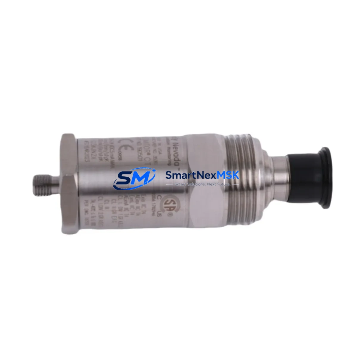
The Bently Nevada 190501-12-00-01 is a seismic velocity transducer engineered for continuous vibration monitoring in rotating machinery protection systems. As legacy 3300 Series installations approach end-of-life or face discontinued spare parts availability, this retrofit-ready unit provides a verified drop-in replacement path that preserves existing wiring infrastructure, monitor rack configurations, and alarm setpoint logic — minimizing engineering rework and unplanned downtime during system modernization.
Industrial facilities operating gas turbines, steam turbines, compressors, pumps, and fans under Bently Nevada 3300 Series protection frameworks can integrate the 190501-12-00-01 directly into existing 3300/16 or 3300/20 monitor slots without reconfiguring the Keyphasor module or rewiring the junction box terminal strip. The transducer’s output signal remains fully compatible with the 3300 Series rack’s velocity input channel, ensuring that existing vibration alarm thresholds, danger setpoints, and trip logic defined in the System 1 condition monitoring software require no modification.
Upgrade Compatibility Table
| Parameter | 190501-12-00-01 Specification | Retrofit Notes |
|---|---|---|
| Series Compatibility | Bently Nevada 3300 Series | Direct slot replacement; no rack modification required |
| Transducer Type | Seismic Velocity (electrodynamic) | Matches OEM output signal type and polarity |
| Mounting Interface | Standard threaded stud mount | Compatible with existing mounting pads and brackets |
| Wiring / Terminal | 2-wire shielded cable, standard connector | Reuse existing field cable; verify shield grounding at junction box |
| Communication | Analog voltage output | No protocol migration required; direct analog input to 3300 monitor |
| Monitor Compatibility | 3300/16, 3300/20 Velocity Monitor | Confirm channel configuration in rack before installation |
| Replacement Recommendation | Direct OEM-equivalent replacement | Recommended for 1:1 swap without engineering change order |
| Commissioning Focus | Zero-speed check, sensitivity verification | Validate mV/mm/s output against monitor channel calibration record |
| Warranty | 12 Months | Covers manufacturing defects; includes pre-shipment functional test report |
Retrofit Planning for Existing Automation Systems
Successful integration of the 190501-12-00-01 into a brownfield 3300 Series installation begins with a thorough review of the existing rack architecture. Most 3300 Series protection panels are built around a modular backplane that houses the power supply module, the Keyphasor 3300/25 or 3300/50 module, velocity monitor cards, and the communication gateway. Before pulling the failed or obsolete transducer, maintenance engineers should document the current channel assignment, confirm the rack address of the velocity monitor card, and photograph the terminal block wiring at the local junction box.
In facilities where the 3300 Series rack feeds data upstream to a DCS — such as a Honeywell Experion PKS or an Emerson DeltaV system — the analog 4–20 mA retransmission output from the 3300 velocity monitor must be verified against the DCS input card scaling. This step is often overlooked during transducer swaps and can result in false readings on the operator HMI screen even when the transducer itself is functioning correctly. Similarly, if the plant uses a System 1 Evolution software platform for online machinery diagnostics, the transducer sensitivity factor stored in the System 1 database should be confirmed to match the 190501-12-00-01 specification before the unit is placed in service.
For installations where the 3300 Series rack also interfaces with a Bently Nevada 3500 Series rack via a TDI (Transient Data Interface) or a shared Modbus RTU link to a PLC — such as an Allen-Bradley ControlLogix or a Siemens S7-300 — the communication link should be tested under live conditions after transducer replacement to confirm that the vibration data tag continues to update correctly in the PLC data table and that no communication fault codes are generated in the rack’s status register.
When the retrofit scope extends beyond a single transducer to include replacement of the 3300/16 velocity monitor card itself, engineers should also plan for reconfiguration of the I/O module address on the backplane, re-entry of alarm and danger setpoints, and a functional trip test before returning the machine to service. In multi-machine protection panels, it is common to find that the Keyphasor signal cable, the proximitor power supply, and the barrier terminal assembly also require inspection during the same maintenance window — making this an efficient opportunity to address deferred maintenance on adjacent components.
Downtime Control During System Migration
Minimizing production impact during a 3300 Series transducer replacement requires a structured pre-outage preparation protocol. The 190501-12-00-01 should be bench-tested and its sensitivity output verified against the calibration certificate before the maintenance window begins. A pre-written channel bypass procedure — using the 3300 monitor’s front-panel bypass switch or a software bypass command issued through System 1 — allows the protection channel to be placed in a non-trip state during the physical swap, preventing a spurious machine trip caused by the open-circuit condition that occurs when the old transducer is disconnected.
Field engineers should prepare a wiring diagram that maps the existing terminal numbers at the junction box to the new transducer’s cable conductors, confirming shield continuity and verifying that the cable run length remains within the 3300 Series specification for velocity transducer cable capacitance. Once the 190501-12-00-01 is installed and the terminal connections are torqued to specification, the bypass should be released and the channel output monitored in real time through the System 1 online display or the 3300 monitor’s front-panel meter before the machine is restarted. This sequence typically allows a complete transducer replacement to be completed within a two-hour planned outage window, preserving the original program logic, HMI alarm graphics, and communication link integrity without requiring any software changes.
Retrofit Support FAQ
Q1: Is the 190501-12-00-01 a direct drop-in replacement for the original Bently Nevada unit in a 3300 Series rack?
Yes. The 190501-12-00-01 is dimensionally and electrically equivalent to the original OEM specification. It mounts using the same threaded stud interface, connects to the existing 2-wire shielded field cable, and produces an output signal that is directly compatible with the 3300/16 and 3300/20 velocity monitor input channels. No rack modification, no wiring change, and no monitor reconfiguration is required for a standard 1:1 replacement.
Q2: What commissioning steps are required after installation?
After physical installation, verify the transducer sensitivity output (mV/mm/s) against the monitor channel calibration record, confirm the channel bypass has been released, and perform a zero-speed vibration check to establish a baseline reading. If the rack feeds a DCS or PLC, confirm that the retransmission output is updating correctly at the upstream system before returning the machine to automatic protection mode.
Q3: How is wiring compatibility confirmed before ordering?
Provide the existing cable part number, connector type, and terminal block layout from your junction box drawing. Our technical team will cross-reference against the 190501-12-00-01 wiring specification and confirm compatibility before shipment. In most 3300 Series installations, the existing field cable is fully reusable.
Q4: What does the 12-month warranty cover, and is a test report included?
The 12-month warranty covers all manufacturing defects in materials and workmanship from the date of shipment. Each unit ships with a pre-shipment functional test report confirming sensitivity output, insulation resistance, and mechanical integrity. Warranty claims are processed directly through our sales team with a typical response time of 48 hours.
© 2026 SMARTNEXMSK. All rights reserved.
Original Source: https://smartnexmsk.com
Contact: sales@smartnexmsk.com | +86 18259474341


