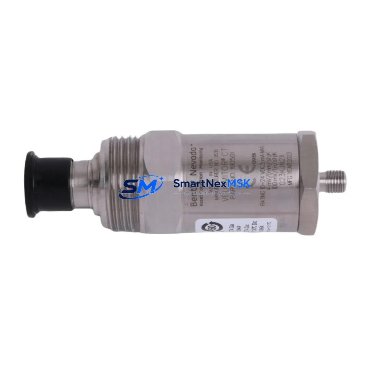
Bently Nevada 190501-12-00-04 Retrofit-Ready Seismic Velocity Transducer for Legacy Control Systems
The Bently Nevada 190501-12-00-04 Velomitor CT is a high-performance seismic velocity transducer engineered for continuous vibration monitoring in rotating machinery protection systems. As original Bently Nevada inventory becomes increasingly scarce, this retrofit-ready replacement unit provides a fully compatible, drop-in solution for facilities operating legacy 3500 Series machinery protection racks, 3300 Series monitors, and TDXnet-based condition monitoring architectures. Whether you are managing a planned upgrade cycle or responding to an unplanned failure, the 190501-12-00-04 is stocked and ready to ship with a 12-month warranty.
This unit delivers a 4–20mA analog output signal with a flat frequency response across the 2–1000 Hz range, making it directly compatible with existing signal conditioning cards in the Bently Nevada 3500/42M Proximitor/Seismic Monitor module. The transducer’s integral cable and connector configuration matches the original factory specification, eliminating the need for field rewiring or junction box modifications during replacement. For sites running the System 1 condition monitoring software platform, the 190501-12-00-04 integrates without requiring driver updates or configuration changes to existing trend and alarm setpoints.
Upgrade Compatibility Table
| Parameter | Details |
|---|---|
| SKU / Part Number | 190501-12-00-04 |
| Brand | Bently Nevada |
| Series Compatibility | 3500 Series, 3300 Series, TDXnet |
| Output Signal | 4–20mA analog |
| Frequency Response | 2–1000 Hz (±3 dB) |
| Connector / Wiring | Drop-in compatible with original 190501 series pinout |
| Mounting Interface | Standard Velomitor CT stud mount; no adapter required |
| Communication Protocol | Analog 4–20mA; compatible with 3500/42M signal input card |
| Replacement Recommendation | Direct drop-in for discontinued 190501-12-00-04 OEM units |
| Commissioning Notes | Verify loop power supply (18–30 VDC), confirm mA zero/span calibration at rack level |
| Warranty | 12 Months from date of shipment |
Retrofit Planning for Existing Automation Systems
Replacing the 190501-12-00-04 in an operating plant requires careful coordination across multiple system layers. Before removing the existing transducer, technicians should document the current 4–20mA loop reading at the Bently Nevada 3500/42M monitor input card and note the active alarm and danger setpoints configured in the rack. If the facility uses a Bently Nevada 3500/20 Rack Interface Module for communication with the DCS or safety system, confirm that the I/O mapping for the affected channel will not trigger a spurious trip during the swap window.
For sites where the 3500 rack communicates over Modbus RTU or Ethernet/IP to a Rockwell Automation ControlLogix or CompactLogix PLC, the channel address and tag mapping in the PLC program should be verified before and after replacement to confirm signal continuity. If the plant uses a Honeywell Experion PKS or Emerson DeltaV DCS as the supervisory layer, the historian tag associated with the vibration channel should be placed in manual substitution mode during the swap to prevent false data from corrupting trend archives.
The physical installation process involves removing the existing Velomitor CT from its stud mount, inspecting the mounting surface for corrosion or thread damage, and torquing the replacement unit to the manufacturer’s specification. The integral cable should be routed to avoid contact with hot surfaces or high-voltage conduit runs. At the junction box, verify that the existing terminal block wiring matches the 190501-12-00-04 pinout before reconnecting. For installations where the original cable has been extended with a Bently Nevada 330130 extension cable, confirm that total cable capacitance remains within the transducer’s specified loop load limit.
Sites upgrading from older 3300 Series monitors to the current 3500 platform as part of a broader modernization project will also need to address the 3500/01 Power Supply module capacity, the 3500/05 System Display and Reset Module configuration, and the 3500/22M Transient Data Interface if transient capture is required. In multi-rack installations, the 3500/92 Communication Gateway Module settings should be reviewed to ensure the new transducer channel is correctly mapped in the gateway’s I/O table. For facilities that also monitor axial position using Bently Nevada 3300 XL 8mm proximity probes, the retrofit plan should confirm that the position channel alarm logic is not inadvertently affected by changes to the adjacent velocity channel configuration.
Downtime Control During System Migration
Minimizing unplanned downtime during a Velomitor CT replacement requires a structured pre-outage checklist. Before the maintenance window opens, the replacement 190501-12-00-04 unit should be bench-tested using a calibrated current source to verify the 4–20mA output linearity across the full measurement range. The test result should be documented and retained as part of the outage record. If the facility’s quality procedure requires a witnessed loop check, arrange for the instrument technician and the control room operator to be available simultaneously during the commissioning step.
During the swap, place the affected machinery protection channel in bypass mode at the 3500/42M monitor to prevent a spurious trip from initiating an emergency shutdown. Confirm with the control room that the bypass is acknowledged in the DCS alarm management system. After installing the replacement transducer and reconnecting the loop wiring, restore the channel from bypass and observe the live 4–20mA reading at the monitor front panel. Compare the reading against the pre-outage baseline to confirm that the replacement unit is performing within the expected range before returning the machine to normal operation.
For facilities that cannot tolerate any interruption to the protection system, a hot-swap procedure using a portable Bently Nevada ADRE 408 DSPi data acquisition system can be used to maintain continuous vibration monitoring on the affected channel while the rack-mounted monitor is temporarily bypassed. This approach preserves the original program logic, maintains HMI display continuity on the System 1 operator screen, and ensures that the communication link to the DCS historian remains active throughout the replacement procedure. Total field time for a prepared crew is typically 45–90 minutes per transducer channel.
Retrofit Support FAQ
Q1: Is the 190501-12-00-04 a direct replacement for the original Bently Nevada OEM part?
Yes. This unit is manufactured to the same dimensional, electrical, and performance specification as the original 190501-12-00-04 Velomitor CT. It is a drop-in replacement with no wiring changes, no adapter plates, and no firmware updates required at the 3500 rack level.
Q2: What commissioning steps are required after installation?
After physical installation and loop wiring reconnection, perform a loop calibration check at the 3500/42M monitor input card. Verify the 4–20mA zero and span against the transducer’s calibration certificate. Confirm that the alarm and danger setpoints in the rack match the pre-outage configuration. Document the as-found and as-left readings in the maintenance management system before returning the channel to service.
Q3: Can this transducer be used with non-Bently Nevada monitoring systems?
Yes. The 190501-12-00-04 outputs a standard 4–20mA analog signal that is compatible with any monitoring system or PLC analog input card that accepts a 4–20mA loop-powered transmitter. It has been successfully integrated with Emerson AMS Machinery Manager, Rockwell Automation Integrated Architecture platforms, and third-party condition monitoring systems using standard analog I/O modules.
Q4: What does the 12-month warranty cover?
The 12-month warranty covers manufacturing defects, electrical failure under normal operating conditions, and output signal deviation beyond the published specification. Each unit is functionally tested and issued with a calibration record prior to shipment. Warranty claims are processed through SMARTNEXMSK’s after-sales support team with a target response time of one business day.
© 2026 SMARTNEXMSK. All rights reserved.
Original Source: https://smartnexmsk.com
Contact: sales@smartnexmsk.com | +86 18259474341


