Bently Nevada 190501-13-99-01 Retrofit-Ready Velocity Transducer for 3500 Series Control Systems
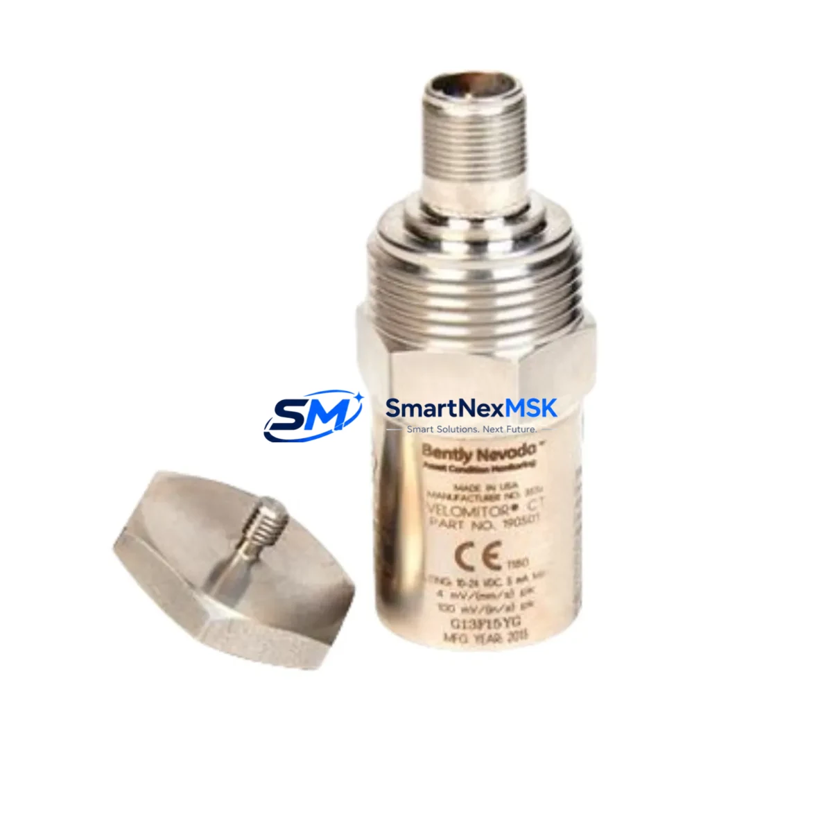
The Bently Nevada 190501-13-99-01 Velomitor CT is a high-performance velocity transducer engineered for seamless integration into Bently Nevada 3500 Series machinery protection systems. Designed as a direct retrofit solution for aging or discontinued velocity sensors, this module supports smooth migration from legacy monitoring architectures without requiring full system replacement. Whether you are upgrading a turbine protection panel, replacing a failed sensor on a compressor train, or modernizing a control cabinet that has been in service for over a decade, the 190501-13-99-01 delivers the signal fidelity and mechanical compatibility required for uninterrupted plant operations.
Industrial facilities running Bently Nevada 3500/42M velocity monitor cards will find this transducer fully compatible with existing barrier terminal strips and field wiring. The Velomitor CT outputs a velocity signal in the industry-standard mV/(mm/s) range, making it directly interchangeable with earlier Velomitor XA and standard Velomitor models in most retrofit scenarios. Before completing the swap, engineers should verify the power supply voltage at the junction box — the 190501-13-99-01 operates on a 18–30 VDC loop supply — and confirm that the 3500 rack’s power module, typically a 3500/15 or 3500/05 power supply, is delivering stable regulated voltage to the I/O termination block.
Upgrade Compatibility Table
| Parameter | Details |
|---|---|
| SKU / Part Number | 190501-13-99-01 |
| Series Compatibility | Bently Nevada 3500 Series Machinery Protection System |
| Replaces / Supersedes | Velomitor XA, standard Velomitor (190501-xx-xx-xx variants) |
| Signal Output | Velocity (mV per mm/s), compatible with 3500/42M monitor card |
| Supply Voltage | 18–30 VDC (loop powered) |
| Connector / Interface | 2-pin MIL-C-5015 style, compatible with existing field cable assemblies |
| Mounting | Stud mount (standard 1/4-28 UNF thread), direct replacement for legacy housings |
| Backplane / Rack Interface | Compatible with 3500 rack I/O termination modules; no rack modification required |
| Communication Protocol | Analog 4–20 mA / voltage signal; no fieldbus reconfiguration required |
| Commissioning Requirement | Verify transducer sensitivity setting in 3500/42M configuration; update if replacing XA variant |
| Warranty | 12 Months from date of shipment |
Retrofit Planning for Existing Automation Systems
A successful retrofit of the 190501-13-99-01 into an operating plant begins well before the physical swap. Start by pulling the existing loop drawing and confirming the field cable pair routed from the junction box to the 3500/42M velocity monitor card. In most installations, the cable terminates at a 3500 I/O termination block — either a standard or galvanic isolation type — and the transducer’s two-wire connection must be verified for polarity before powering up. If the legacy sensor was a Velomitor XA, note that the sensitivity coefficient stored in the 3500/42M configuration software (System 1 or Rack Configuration Software) may need to be updated to match the 190501-13-99-01 output specification.
For facilities running a broader Bently Nevada 3500 rack, the retrofit window is also an ideal time to audit adjacent modules. The 3500/22M transient data interface, 3500/40M proximitor monitor, and 3500/45 position monitor cards share the same rack backplane and power distribution. If any of these modules show firmware version mismatches or degraded calibration records, scheduling their inspection alongside the velocity transducer replacement reduces total downtime. Similarly, the 3500/92 communication gateway — which bridges the 3500 rack to a DCS or SCADA platform via Modbus or OPC — should be confirmed operational before the new transducer is brought online, as a communication fault during commissioning can mask valid alarm states.
On the field side, inspect the armored cable and conduit run from the machine bearing housing to the junction box. Velomitor CT sensors are sensitive to cable shield integrity; a compromised drain wire or broken shield continuity will introduce noise into the velocity signal and trigger nuisance alarms on the 3500/42M card. Replace any degraded cable sections with shielded twisted-pair rated for the ambient temperature of the installation zone. At the junction box, verify that the terminal block — often a Phoenix Contact or Weidmüller DIN-rail type — is free of corrosion and that the barrier terminals, if present, are within their rated voltage and current specifications.
If the retrofit is part of a broader control cabinet upgrade that also involves replacing a legacy Bently Nevada 1900/65A standalone monitor or a 3300 series rack with a modern 3500 system, additional planning is required. The 1900/65A outputs a 4–20 mA velocity signal directly to the DCS analog input card, whereas the 3500/42M communicates alarm and trip states digitally through the 3500/92 gateway. This protocol migration requires updating the DCS tag database, revising the HMI faceplate for the affected machine train, and re-mapping the hardwired relay outputs from the 3500 rack to the emergency shutdown (ESD) system. Coordinate with the control room team to freeze HMI display updates during the cutover window to prevent operator confusion.
Downtime Control During System Migration
Minimizing production downtime during a velocity transducer retrofit requires a structured pre-outage preparation plan. At least 48 hours before the scheduled maintenance window, export the full 3500 rack configuration from the Rack Configuration Software and store a backup copy on a secure engineering workstation. This configuration file contains all transducer sensitivity values, alarm setpoints, time-delay settings, and relay output assignments — losing it during a firmware update or module swap can extend the outage by hours.
During the physical replacement, keep the 3500 rack powered and in bypass mode where plant safety procedures permit. The 3500 system supports individual channel bypass through the front-panel keyswitch or via software, allowing the velocity channel to be taken out of service while adjacent channels — such as radial vibration from a 3500/40M proximitor monitor or axial position from a 3500/45 — continue to protect the machine. This approach preserves overall machinery protection coverage and satisfies most plant safety management of change (MOC) requirements.
After installing the 190501-13-99-01, perform a bench-level signal check using a portable calibration shaker or signal simulator before reconnecting the field cable. Confirm that the 3500/42M card reads the expected velocity value within the calibrated range. Once the field cable is reconnected and the channel is taken out of bypass, verify that the System 1 software (or the plant’s condition monitoring platform) is receiving live data from the new transducer and that no latent alarms are present. Document the as-left configuration, including the transducer serial number, installation torque, and cable shield termination point, in the plant’s maintenance management system (CMMS) before closing the work order.
Retrofit Support FAQ
Q1: Is the 190501-13-99-01 a direct drop-in replacement for the Velomitor XA?
In most installations, yes. The mechanical mounting thread, connector type, and cable interface are compatible. However, the sensitivity coefficient in the 3500/42M configuration must be verified and updated if the XA variant used a different mV/(mm/s) rating. Always compare the transducer datasheet values before finalizing the configuration.
Q2: What wiring changes are required during installation?
The 190501-13-99-01 uses a standard 2-wire loop-powered connection. In most cases, existing field cables can be reused if they are in good condition and the shield integrity is intact. Confirm polarity at the I/O termination block and verify that the barrier terminal (if installed) is rated for the transducer’s supply voltage range of 18–30 VDC.
Q3: Has this unit been tested before shipment?
Yes. Every 190501-13-99-01 unit undergoes functional output verification and signal linearity testing prior to shipment. A test report is available upon request. All units are covered by a 12-month warranty from the date of shipment, covering manufacturing defects and signal output failures under normal operating conditions.
Q4: Can this transducer be used with a Bently Nevada 3300 series rack or a 1900/65A standalone monitor?
The 190501-13-99-01 is optimized for the 3500 series architecture. Use with a 3300 series rack or 1900/65A monitor requires verification of the input impedance and supply voltage compatibility of the target monitor. Contact our technical team with your existing monitor model number for a compatibility assessment before ordering.
© 2026 SMARTNEXMSK. All rights reserved.
Original Source: https://smartnexmsk.com
Contact: sales@smartnexmsk.com | +86 18259474341


