Bently Nevada 190501-14-00-04 Retrofit-Ready Velocity Transducer for 3500 Series Control Systems
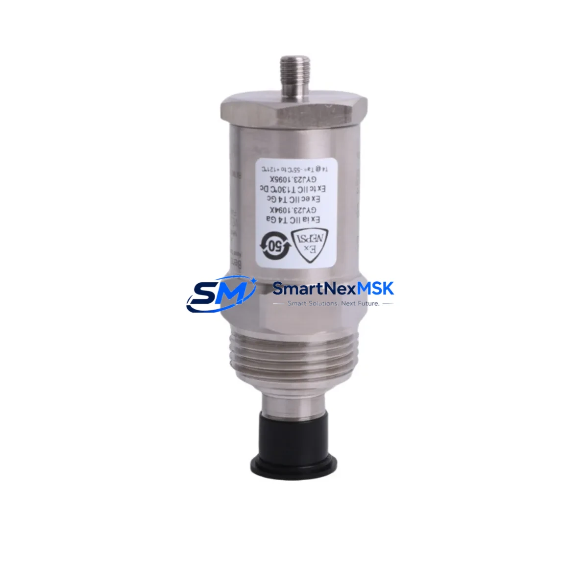
The Bently Nevada 190501-14-00-04 Velomitor CT is a compact, loop-powered velocity transducer engineered for continuous vibration monitoring on rotating machinery. As legacy 3500 series installations age and OEM support for this SKU becomes increasingly limited, plant engineers and reliability teams are actively seeking verified retrofit-ready replacements that preserve existing wiring, rack architecture, and program logic without requiring a full system overhaul.
SMARTNEXMSK maintains verified stock of the 190501-14-00-04 and supports customers through the complete retrofit cycle — from pre-shipment compatibility verification to post-installation commissioning guidance. Each unit ships with a 12-month warranty and undergoes functional testing prior to dispatch.
Upgrade Compatibility Table
| Parameter | 190501-14-00-04 (This Unit) | Retrofit Notes |
|---|---|---|
| Output Signal | 4–20 mA loop-powered | Direct drop-in; no signal conditioner change required |
| Frequency Range | 2–1000 Hz | Verify machinery speed range before installation |
| Mounting Interface | M8 × 1.25 threaded stud | Compatible with standard Velomitor CT mounting pads |
| Rack Compatibility | Bently Nevada 3500 Series | Plug-compatible with 3500/42M, 3500/45, 3500/46M monitor cards |
| Cable / Connector | Integral cable, MIL-C-5015 connector | Match existing field cable termination; no re-wiring needed |
| Communication Protocol | Analog (4–20 mA) | No protocol migration required; compatible with existing I/O cards |
| Power Supply | 18–30 VDC loop-powered | Confirm rack power module (e.g., 3500/15 Power Supply) output voltage |
| Replacement Recommendation | Direct OEM-equivalent | No firmware or configuration changes required in 3500 rack |
| Commissioning Focus | Zero-speed check, full-speed vibration baseline | Compare against historical trend data in System 1 software |
| Warranty | 12 Months | Covered from date of shipment; includes functional test certificate |
Retrofit Planning for Existing Automation Systems
Replacing the 190501-14-00-04 in an operating plant requires careful coordination across multiple system layers. The 3500 series rack typically houses a combination of monitor cards, I/O modules, and communication interfaces that must remain undisturbed during transducer swap-out. Before beginning the retrofit, engineers should confirm that the 3500/15 Power Supply module is delivering stable 24 VDC to the transducer loop, and that the associated 3500/42M Proximitor/Seismic Monitor or 3500/45 Position Monitor card is configured for velocity input mode.
Terminal block wiring should be documented prior to disconnection. The 190501-14-00-04 uses a two-wire loop configuration; polarity must be maintained at the 3500 I/O module terminal strip. If the installation includes a 3500/20 Rack Interface Module (RIM) for Modbus or Ethernet/IP communication to a DCS or SCADA layer, no changes to the communication link are required — the monitor card handles signal conversion internally.
For plants running Bently Nevada System 1 condition monitoring software, the transducer channel configuration (sensitivity, full-scale range, alert/danger setpoints) is stored at the monitor card level, not the transducer. This means the replacement 190501-14-00-04 will inherit the existing channel configuration automatically, eliminating the need for software re-commissioning in most cases.
Where the retrofit is part of a broader control cabinet upgrade — for example, migrating from a legacy 3300 series rack to the 3500 platform — additional planning is required. The 3500/22M Transient Data Interface may need to be added to capture startup and coastdown data for the upgraded machinery train. Similarly, if the plant is expanding I/O capacity, a 3500/60 Temperature Monitor or additional 3500/40M Proximitor Monitor cards may be installed in adjacent rack slots during the same maintenance window, minimizing total downtime.
For sites using a Keyphasor module (3500/25) for phase reference, verify that the Keyphasor signal is correctly routed to all dependent monitor cards after the transducer replacement. This is particularly important for machinery trains where phase-referenced vibration analysis is used for balancing or alignment diagnostics.
If the plant’s control architecture includes a Rockwell ControlLogix or CompactLogix PLC receiving vibration data via the 3500 RIM over EtherNet/IP, confirm that the PLC tag mapping and alarm logic remain valid after the transducer swap. In most cases, no PLC program changes are required, but a functional test of the alarm annunciation path is recommended before returning the machine to service.
Downtime Control During System Migration
Minimizing unplanned downtime is the primary concern for any rotating machinery retrofit. The 190501-14-00-04 is designed as a direct drop-in replacement, which means the physical swap can typically be completed within a single planned maintenance window — often less than two hours for an experienced instrumentation technician.
To protect original program logic and alarm setpoints, SMARTNEXMSK recommends the following sequence: First, export the current channel configuration from the 3500 Rack Configuration Software and save a backup to a secure location. Second, document all terminal wiring at the I/O module before disconnecting the old transducer. Third, install the replacement 190501-14-00-04, restore wiring per the documented termination diagram, and power up the rack. Fourth, verify the 4–20 mA loop current at the monitor card input using a calibrated loop calibrator. Fifth, confirm that the System 1 trend display shows a valid, stable vibration reading before releasing the machine for restart.
For critical machinery where continuous monitoring is required, a temporary portable vibration analyzer can be used to maintain surveillance during the brief period when the permanent monitoring channel is offline. This approach preserves field control continuity and satisfies most plant safety management requirements without requiring a formal bypass permit for the monitoring system.
Where the retrofit is being performed as part of a scheduled turnaround, the opportunity should be taken to inspect and if necessary replace associated components such as the interconnect cable assembly and junction box terminal blocks, which may have degraded over the same service period as the original transducer. Replacing these items concurrently avoids a second maintenance intervention in the near term.
Retrofit Support FAQ
Q1: Is the 190501-14-00-04 a direct replacement for the original Bently Nevada Velomitor CT, or are there wiring or configuration differences I need to account for?
A: The 190501-14-00-04 is a direct OEM-equivalent replacement. It uses the same two-wire 4–20 mA loop interface, the same M8 threaded mounting stud, and the same MIL-spec connector as the original unit. No wiring changes or monitor card reconfiguration are required in a standard 3500 series installation.
Q2: How do I verify compatibility with my specific 3500 rack configuration before ordering?
A: Provide your rack slot layout, monitor card model numbers (e.g., 3500/42M, 3500/45), and the existing transducer cable part number. SMARTNEXMSK’s technical team will confirm compatibility and flag any interface considerations before shipment. Contact us at sales@smartnexmsk.com.
Q3: What pre-shipment testing is performed, and what documentation is included?
A: Every 190501-14-00-04 unit undergoes functional loop testing prior to dispatch. A test certificate confirming output signal integrity is included with each shipment. The unit is covered by a 12-month warranty from the date of shipment.
Q4: Can this unit be used in a migration from a 3300 series rack to the 3500 platform?
A: Yes. The 190501-14-00-04 is compatible with the 3500 series rack architecture. If you are migrating from a 3300 series installation, the transducer itself does not change — the primary migration work involves replacing the rack, monitor cards, and I/O modules. SMARTNEXMSK can supply associated 3500 series components to support a complete rack migration project.
© 2026 SMARTNEXMSK. All rights reserved.
Original Source: https://smartnexmsk.com
Contact: sales@smartnexmsk.com | +86 18259474341


