Bently Nevada 190501-15-99-CN Retrofit Velocity Sensor: Seamless Compatibility for Legacy System Upgrades
The Bently Nevada 190501-15-99-CN Velomitor CT is a high-performance seismic velocity transducer engineered for direct retrofit into existing Bently Nevada 3500 Series continuous machinery monitoring systems. As aging Velomitor and proximity probe installations approach end-of-life or face discontinued spare parts availability, the 190501-15-99-CN provides a validated, drop-in compatible replacement path that preserves existing wiring infrastructure, terminal block assignments, and monitor channel configurations — minimizing engineering rework and unplanned downtime.
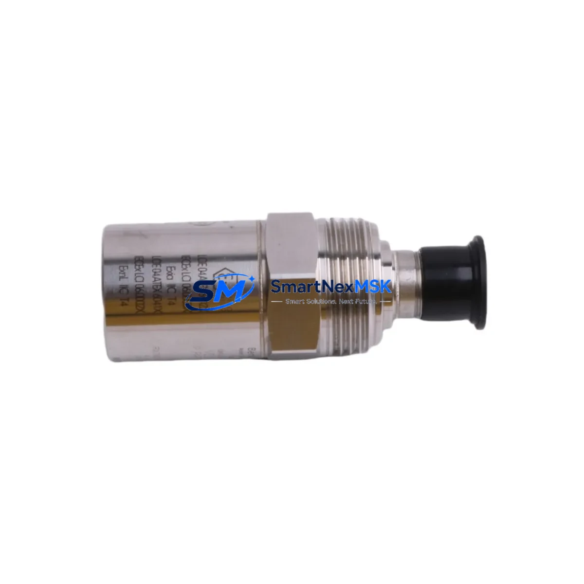
Designed for industrial environments where control continuity is non-negotiable, this transducer delivers broadband velocity measurement across rotating machinery including turbines, compressors, pumps, and motors. Its rugged stainless-steel housing and integral cable assembly are dimensionally compatible with standard Bently Nevada mounting provisions, allowing field technicians to complete a swap without modifying the existing conduit runs or junction box layouts.
Upgrade Compatibility Table
| Parameter | 190501-15-99-CN Specification | Retrofit Notes |
|---|---|---|
| Replaces / Supersedes | 190501-15-99, 190501-15-00-CN | Confirm suffix compatibility with monitor firmware revision |
| Compatible Monitor | Bently Nevada 3500/42M, 3500/42E, 3500/45 | Verify rack slot assignment and channel pairing |
| Output Signal | Velocity (mV/mm/s or mV/in/s) | Match transducer sensitivity to monitor input card scaling |
| Connector / Interface | Integral 2-conductor shielded cable, MIL-spec connector | Inspect existing junction box terminal strip for corrosion before reconnection |
| Mounting | 1/4-28 UNF stud mount | Clean mounting surface; apply thread-locking compound per OEM torque spec |
| Power Supply | 18–30 VDC (loop-powered) | Verify 3500 rack power supply capacity before adding channels |
| Communication Protocol | Analog 4–20 mA / voltage output | No protocol migration required; analog signal chain preserved |
| Operating Temperature | –40°C to +121°C | Suitable for high-temperature turbine bearing housings |
| Installation Qualification | Factory acceptance test included | Perform loop check and channel calibration after installation |
| Warranty | 12 Months | Covers manufacturing defects; includes pre-shipment functional test report |
Retrofit Planning for Existing Automation Systems
Successful integration of the 190501-15-99-CN into a legacy monitoring architecture requires a structured pre-installation review. Begin by auditing the existing 3500 Series rack configuration: confirm the installed 3500/20 rack power supply module can support the additional transducer load, and verify that the 3500/42M or 3500/42E velocity monitor card firmware is at a revision level that recognizes the -CN suffix variant. In multi-channel installations, cross-reference the channel-to-transducer mapping documented in the original system FAT (Factory Acceptance Test) report.
Terminal wiring should be verified against the original loop drawing. The 190501-15-99-CN uses a standard two-conductor shielded cable terminated at the 3500 I/O module’s barrier terminal strip. If the existing installation used a 3500/92 or 3500/93 I/O module, confirm that the barrier terminal block pinout matches the replacement transducer’s polarity convention. Shield grounding must follow Bently Nevada’s single-point grounding practice to prevent ground loop interference on the velocity signal.
For sites running Bently Nevada System 1 or System 1 Evolution software, the transducer database entry should be updated to reflect the new part number. The software’s transducer library supports the Velomitor CT family natively, so no custom sensitivity curve entry is required — simply select the correct model from the drop-down and confirm the mV/mm/s scaling matches the monitor card’s input range. If the site uses a third-party DCS historian such as an Emerson DeltaV or Honeywell Experion integration via OPC-DA or OPC-UA, verify that the tag mapping for the affected channel remains intact after the transducer swap.
In installations where the 190501-15-99-CN replaces a proximity probe and Bently Nevada 3300 XL 8mm proximitor system on a retrofit basis, additional engineering is required: the monitor card must be changed from a proximity (eddy-current) input type to a seismic velocity input type, and the 3500 rack’s configuration software (Rack Configuration) must be used to reprogram the channel. This typically involves swapping the 3500/40M proximity monitor card for a 3500/42M velocity monitor card, updating the I/O module, and re-running the full channel calibration sequence. The 3500/15 power supply module and 3500/22M transient data interface module are unaffected by this change and can remain in place.
Before returning the machine to service, perform a complete loop verification: apply a known reference vibration signal using a calibrated shaker or signal simulator, confirm the System 1 trend display reflects the correct engineering units, and validate that the 3500 rack’s alert and danger setpoints are correctly configured per the machinery OEM’s vibration severity guidelines. Document the as-left calibration data and retain it with the machine’s maintenance record.
Downtime Control During System Migration
Minimizing production impact during a Velomitor CT replacement requires advance preparation. Before the maintenance window opens, pre-stage the 190501-15-99-CN alongside any ancillary items — replacement terminal screws, cable glands, and a calibrated torque wrench — at the work site. Download and archive the current 3500 rack configuration file from the Rack Configuration software so that the original channel parameters can be restored immediately if the replacement transducer exhibits an unexpected fault during commissioning.
Where the process permits, place the affected 3500 monitor channel in bypass mode before disconnecting the old transducer. This prevents a spurious danger trip from propagating to the machine’s protective relay logic or DCS interlock system during the swap interval. Confirm with the control room operator that the bypass is acknowledged in the alarm management system and that a time-limited bypass permit has been issued per the site’s management-of-change procedure.
The physical transducer exchange — unmounting the old unit, cleaning the mounting pad, installing and torquing the 190501-15-99-CN, and reconnecting the cable — typically requires 20 to 45 minutes for a single-channel replacement on an accessible bearing housing. After reconnection, remove the channel bypass, observe the live vibration trend in System 1 for a minimum of five minutes at steady-state operating speed, and confirm that the reading is stable and within the expected baseline range before closing the work order. This structured approach consistently achieves single-shift completion for single-channel Velomitor CT replacements without requiring a full machine shutdown.
Retrofit Support FAQ
Q1: Is the 190501-15-99-CN a direct drop-in replacement for the 190501-15-99 without any monitor reconfiguration?
In most cases, yes. The -CN suffix denotes a connector variant; the electrical output characteristics and sensitivity are identical to the standard 190501-15-99. However, you should verify that the cable connector at the junction box end is compatible with your existing field wiring termination. If the original installation used a different connector style, a field-wireable adapter or a short pigtail adapter cable may be required. No changes to the 3500 monitor card configuration are typically needed.
Q2: What pre-shipment testing is performed on the 190501-15-99-CN?
Each unit undergoes a functional output test and sensitivity verification before shipment. A test report confirming the measured sensitivity (mV/mm/s) against the published specification is included with the shipment. The 12-month warranty covers manufacturing defects identified during installation or normal operation within the rated environmental envelope.
Q3: Can this transducer be used with a Bently Nevada 3300 Series monitor instead of the 3500 Series?
The 190501-15-99-CN is optimized for 3500 Series monitor cards. While the analog output signal is electrically compatible with 3300 Series velocity monitor inputs, Bently Nevada does not formally cross-qualify Velomitor CT units across monitor generations. For 3300 Series installations, consult the monitor card’s input specification and confirm that the transducer’s output impedance and sensitivity fall within the card’s accepted input range before proceeding.
Q4: What is the lead time and how is inventory availability confirmed?
Stock availability is confirmed at the time of order. In-stock units ship within 1–3 business days. For urgent replacement requirements, contact our sales team directly to confirm real-time inventory status and expedited shipping options. All units are supplied with a 12-month warranty from the date of shipment.
© 2026 SMARTNEXMSK. All rights reserved.
Original Source: https://smartnexmsk.com
Contact: sales@smartnexmsk.com | +86 18259474341


