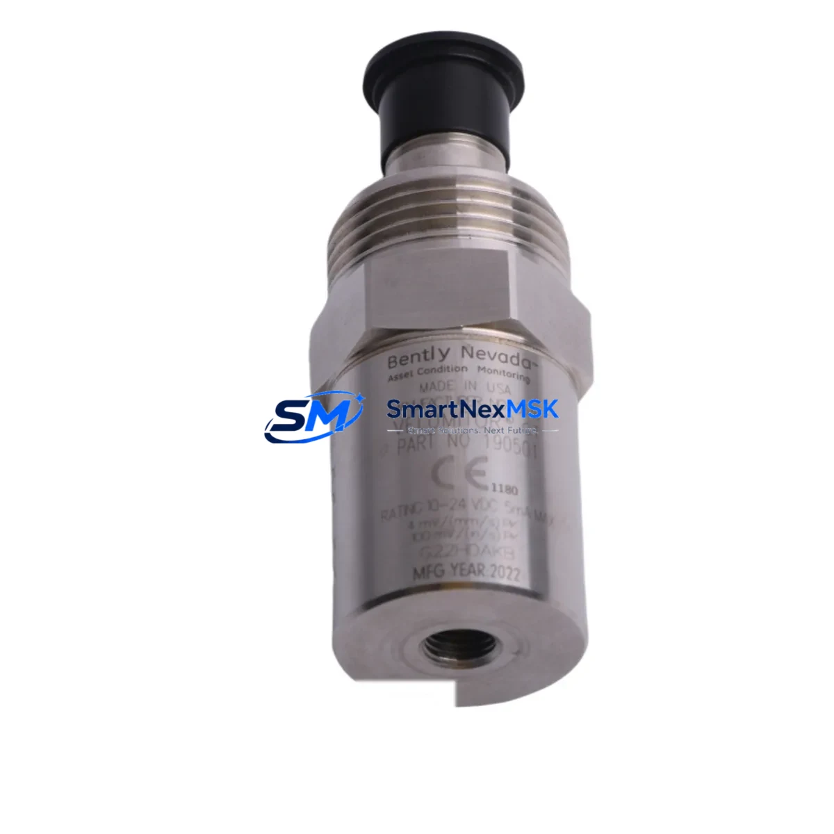
Bently Nevada 190501-18-00-CN Retrofit Velomitor CT for 3500 Series Control Systems
The Bently Nevada 190501-18-00-CN Velomitor CT is a compact, loop-powered velocity transducer engineered for continuous vibration monitoring on rotating machinery. Designed as a retrofit-ready replacement for aging or discontinued sensors in Bently Nevada 3500 Series machinery protection systems, this unit delivers a direct drop-in upgrade path with no rack reconfiguration required. Whether you are recovering a failed sensor on a critical compressor train, upgrading a legacy monitoring loop, or restoring a mothballed production line, the 190501-18-00-CN provides the signal integrity and mechanical compatibility your system demands.
SMARTNEXMSK maintains verified stock of the 190501-18-00-CN and ships with a 12-month warranty covering manufacturing defects and functional performance. Each unit undergoes pre-shipment functional testing to confirm output sensitivity, frequency response, and connector integrity before dispatch.
Upgrade Compatibility Table
| Parameter | 190501-18-00-CN Specification | Retrofit Notes |
|---|---|---|
| Transducer Type | Velomitor CT (velocity, loop-powered) | Direct replacement for standard Velomitor CT variants |
| Output Sensitivity | 100 mV/in/s (4 mV/mm/s) | Verify rack channel scaling in 3500/42M or 3500/42E monitor card |
| Frequency Response | 2 Hz – 1,000 Hz (±3 dB) | Confirm alarm setpoints match original sensor bandwidth |
| Supply Voltage | 18–30 VDC (loop-powered) | Check 3500 rack power supply capacity; 3500/15 or 3500/05 PSU typically sufficient |
| Connector | 2-pin MIL-C-5015 style | Reuse existing field cable; inspect connector pins for corrosion before reconnection |
| Mounting | 1/4-28 UNF stud mount | Clean mounting surface; torque to OEM specification to avoid resonance errors |
| Housing | Stainless steel, IP67 | Suitable for outdoor and wash-down environments |
| Compatible Monitor Cards | 3500/42M, 3500/42E, 3500/45 | No firmware update required for standard channel configuration |
| Communication Compatibility | Analog 4–20 mA / voltage output to rack | No protocol migration needed; rack handles signal conditioning |
| Warranty | 12-Month Warranty — covers manufacturing defects and functional performance | |
Retrofit Planning for Existing Automation Systems
Replacing the 190501-18-00-CN within an operating plant requires a structured approach to avoid unplanned downtime and protect existing program logic. Before breaking any connections, document the current channel configuration in the Bently Nevada 3500 Rack Configuration Software and export a backup of all monitor settings, including full-scale ranges, alarm setpoints, and OK relay logic.
In most installations, the 190501-18-00-CN feeds signal into a 3500/42M Velocity Monitor or 3500/42E Velocity/Acceleration Monitor card seated in a standard 3500 Series rack. The rack itself — typically a 3500/05 Rack Interface Module chassis — communicates upstream via a 3500/22M Transient Data Interface or directly to a DCS through a 3500/92 Communication Gateway using Modbus RTU or Ethernet/IP. Confirm that the gateway configuration does not require re-mapping after sensor swap; in most cases, the channel address and tag name remain unchanged.
On the field side, inspect the existing two-conductor shielded cable run from the junction box to the sensor mounting pad. If the cable shows insulation degradation or moisture ingress — common in installations older than ten years — replace it with a new run of Belden 9501 or equivalent low-capacitance instrumentation cable before installing the new sensor. Verify that the shield drain wire is grounded at one end only (typically at the rack end) to prevent ground loops that can corrupt vibration readings.
For plants running a System 1 Evolution or System 1 Optimizer condition monitoring platform, the sensor tag will already be mapped in the historian. After physical replacement, perform a bump test or use a calibrated shaker to confirm the new sensor’s output matches the expected sensitivity value before releasing the machine to service. Update the System 1 asset record with the new sensor serial number and installation date for traceability.
If the retrofit is part of a broader control cabinet upgrade — for example, migrating from a legacy Bently Nevada 7200 Series or 3300 Series monitoring system to the 3500 platform — additional planning is required. The 3500 rack uses a different backplane pinout and power distribution scheme than the 3300 chassis, so a new 3500/15 Power Supply and rack assembly will be needed. I/O terminal blocks, typically 3500 Series I/O Modules with removable terminal strips, should be pre-wired and tested on the bench before installation to minimize field time. HMI screens tied to the old system’s OPC server tags will need to be remapped to the new 3500 Modbus register map or Ethernet/IP tag structure.
Where a Keyphasor module (such as the 3500/25) is present in the rack for phase reference, verify that the Keyphasor signal is intact and correctly configured after the velocity sensor swap, as some alarm logic is phase-referenced. Programming cables such as the Bently Nevada 990-05-70-01-00 RS-232 interface may be needed for older rack firmware updates during the migration window.
Downtime Control During System Migration
Minimizing production impact during a sensor replacement on a critical machine requires pre-staging all materials and completing as much bench work as possible before the maintenance window opens. For the 190501-18-00-CN swap, the physical replacement itself typically takes under 30 minutes if the mounting surface is accessible and the cable connector is in good condition. The majority of migration time is consumed by configuration verification, bump testing, and alarm reinstatement.
Where process conditions allow, consider placing the affected 3500 monitor channel in Bypass mode via the rack front panel or System 1 software before disconnecting the old sensor. This prevents a spurious OK relay dropout from triggering a plant-wide interlock or DCS alarm during the swap interval. Document the bypass action in the plant’s management of change (MOC) system and set a hard time limit — typically no more than two hours — before the bypass must be cleared or escalated.
If the machine cannot be taken offline, a hot-swap procedure using a pre-terminated replacement sensor and a pre-staged cable assembly can reduce field exposure time to under ten minutes. Coordinate with the control room operator to monitor the DCS trend display for the affected channel during the swap and confirm signal restoration immediately after reconnection. Once the new 190501-18-00-CN is installed and the channel is out of bypass, verify that the OK LED on the monitor card is illuminated and that the vibration reading is within the expected baseline range before closing the work order.
Retain the removed sensor for failure analysis if the replacement was triggered by an alarm condition rather than a scheduled interval. Shipping the failed unit to a calibration laboratory for post-mortem inspection can provide data to support a root-cause analysis and inform future preventive maintenance intervals.
Retrofit Support FAQ
Q1: Is the 190501-18-00-CN a direct drop-in replacement for other Velomitor CT variants?
Yes. The 190501-18-00-CN is mechanically and electrically compatible with other Velomitor CT models sharing the same 1/4-28 UNF stud mount and 2-pin MIL-style connector. Confirm output sensitivity (100 mV/in/s) matches the channel scaling configured in your 3500/42M or 3500/42E monitor card before installation. No rack firmware changes are required for a like-for-like swap.
Q2: What wiring checks should I perform before connecting the new sensor?
Inspect the field cable for continuity, insulation resistance (minimum 100 MΩ to ground), and shield integrity. Verify that the connector pins are clean and free of corrosion. Confirm supply voltage at the connector is within the 18–30 VDC operating range before mating. Incorrect polarity will not damage the sensor but will result in no output signal.
Q3: How do I verify compatibility with my existing 3500 Series rack configuration?
Open the 3500 Rack Configuration Software and navigate to the channel assigned to the velocity sensor. Confirm the transducer type is set to “Velomitor” and the full-scale range matches the 190501-18-00-CN sensitivity. If the channel was previously configured for a different transducer type (e.g., a proximity probe or accelerometer), a configuration change and re-download to the rack will be required before the sensor will produce valid readings.
Q4: What does the 12-month warranty cover, and what is the return process?
The 12-month warranty covers manufacturing defects and functional performance failures under normal operating conditions. It does not cover damage resulting from incorrect installation, overvoltage, or mechanical impact. To initiate a warranty claim, contact SMARTNEXMSK with the order number, sensor serial number, and a description of the failure. A replacement unit will be dispatched after fault confirmation, and a prepaid return label will be provided for the defective unit.
© 2026 SMARTNEXMSK. All rights reserved.
Original Source: https://smartnexmsk.com
Contact: sales@smartnexmsk.com | +86 18259474341


