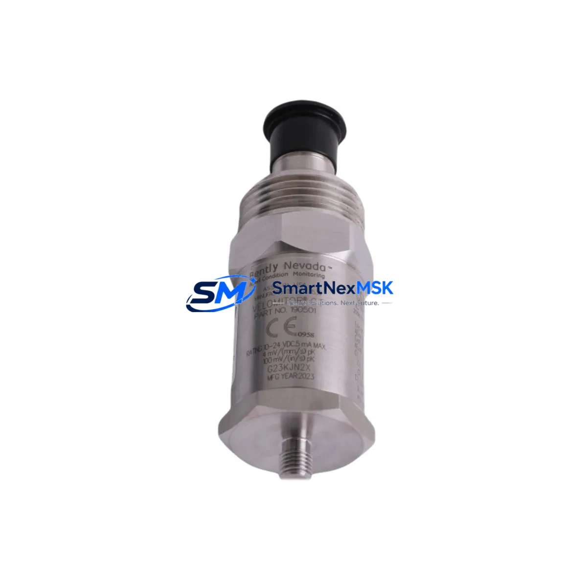
Bently Nevada 190501-20-00-04 Retrofit-Ready Velomitor CT for 3500 Series Control Systems
The Bently Nevada 190501-20-00-04 Velomitor CT is a high-performance seismic velocity transducer engineered for direct retrofit into existing 3500 Series machinery protection systems. As legacy vibration monitoring infrastructure reaches end-of-life, plant engineers and reliability teams increasingly require a drop-in replacement that preserves original wiring topology, signal conditioning compatibility, and alarm setpoint integrity — without forcing a full system redesign. The 190501-20-00-04 addresses precisely this need, delivering a smooth upgrade path for facilities operating continuous process equipment such as turbines, compressors, pumps, and fans where unplanned downtime carries significant operational and financial risk.
Designed to interface directly with the Bently Nevada 3500/42M Proximitor/Seismic Monitor module, the 190501-20-00-04 outputs a velocity signal compatible with the standard 3500 rack architecture. Engineers replacing worn or failed Velomitor CT units can retain existing Belden shielded cable runs, terminal block assignments, and junction box configurations, dramatically reducing field labor time and the risk of wiring errors during changeover. The transducer’s internal electronics are sealed against moisture, dust, and hydrocarbon contamination, making it suitable for outdoor installations and harsh process environments where legacy sensors have historically degraded.
Upgrade Compatibility Table
| Parameter | Details |
|---|---|
| SKU / Part Number | 190501-20-00-04 |
| Brand / OEM | Bently Nevada |
| Compatible System | Bently Nevada 3500 Series Machinery Protection |
| Monitor Module | 3500/42M Proximitor/Seismic Monitor |
| Replaces / Supersedes | 190501-20-00-01, 190501-20-00-02, earlier Velomitor CT variants |
| Signal Output | Velocity (mV/mm/s), compatible with 3500 rack signal conditioning |
| Connector / Interface | 2-pin MIL-C-5015 style, matches legacy Velomitor wiring |
| Installation | Direct bolt-on retrofit; no bracket modification required |
| Communication Compatibility | Passive analog; integrates with System 1 software via 3500 rack |
| Retrofit Recommendation | Replace in pairs on critical machinery for balanced monitoring |
| Commissioning Notes | Verify gap voltage, sensitivity scaling, and alarm setpoints post-installation |
| Warranty | 12 Months from date of shipment |
Retrofit Planning for Existing Automation Systems
A successful retrofit of the 190501-20-00-04 into an operating plant begins well before the physical swap. Reliability engineers should first audit the existing 3500 rack configuration, confirming that the 3500/42M monitor card firmware is current and that the rack’s power supply module — typically a 3500/15 Power Supply — is delivering stable ±24 VDC within specification. Voltage sag at the rack backplane is a common but overlooked cause of false vibration alarms after transducer replacement, and should be measured under full I/O load before the new Velomitor CT is energized.
Terminal block wiring should be documented with photographs prior to disconnection. The 190501-20-00-04 uses the same two-conductor shielded cable topology as its predecessors, but shield grounding practice at the junction box must be verified — single-point grounding at the monitor end is mandatory to prevent ground loop interference that can corrupt velocity readings. If the existing cable run exceeds 300 meters, engineers should confirm that cable capacitance remains within the transducer’s drive capability specification before reuse.
For facilities running Bently Nevada System 1 condition monitoring software, the transducer replacement does not require a database reconfiguration provided the sensitivity value (mV/mm/s) of the 190501-20-00-04 matches the previously configured channel parameter. If the outgoing unit was a non-standard sensitivity variant, the System 1 channel configuration must be updated before the new transducer is placed in service. HMI screens displaying vibration trend data should be reviewed post-commissioning to confirm that the engineering unit scaling and alarm visualization remain consistent with pre-retrofit baselines.
Where the retrofit is part of a broader control system modernization — for example, migrating from a legacy 3300 Series rack to the current 3500 architecture — additional components will typically be required. The 3500/20 Rack Interface Module governs communication between the protection rack and the plant DCS or SCADA layer, and its configuration must reflect the updated I/O channel map. If the plant historian or DCS is connected via Modbus TCP or OPC-DA, the tag mapping for the replaced channel should be validated against the new transducer’s output range. In parallel migrations involving simultaneous replacement of proximity probes, extension cables such as the 330130-080-00-00, and Proximitor sensors on the same shaft, a phased commissioning sequence is strongly recommended to isolate variables and simplify fault diagnosis.
Facilities upgrading multiple measurement points in a single outage window often find it efficient to pre-stage a complete spare rack assembly — including the 3500/22M Transient Data Interface and any required 3500/32 4-Channel Relay modules — so that the replacement rack can be pre-configured, loop-checked, and ready for cutover before the process unit is taken offline. This approach, combined with pre-tested 190501-20-00-04 transducers verified on a bench signal simulator, consistently delivers the shortest possible outage duration.
Downtime Control During System Migration
Minimizing production loss during a Velomitor CT replacement requires a structured pre-outage preparation protocol. The 190501-20-00-04 should be bench-tested against a known reference signal source before it reaches the field, confirming sensitivity, frequency response, and output linearity. Shipping the unit with a calibration certificate and test report allows the site acceptance team to verify compliance without repeating full characterization on-site, compressing commissioning time to a final loop check and alarm trip test.
Original program logic in the associated safety instrumented system or DCS controller should be exported and archived before any field wiring is disturbed. If the 3500 rack is connected to a Triconex or similar SIS controller via hardwired relay outputs from the 3500/32 module, the relay output states must be confirmed in bypass mode before the transducer is de-energized to prevent spurious process trips. For turbine applications where the 3500 rack also monitors axial position via 3300 XL 8mm proximity probes, the axial channel should remain in service throughout the velocity transducer swap to maintain continuous shaft protection.
Post-installation, a 30-minute observation period at normal operating speed — with System 1 trend data recording active — is recommended before returning the machinery protection system to automatic trip mode. This window allows engineers to confirm that the 190501-20-00-04 is tracking actual machine vibration rather than electrical noise, and that the overall vibration level is consistent with the pre-outage baseline. Any deviation greater than 10% from the historical trend should be investigated before the bypass is lifted.
Retrofit Support FAQ
Q: Is the 190501-20-00-04 a direct drop-in replacement for earlier Velomitor CT part numbers?
A: Yes. The 190501-20-00-04 is dimensionally and electrically compatible with earlier Velomitor CT variants including the 190501-20-00-01 and 190501-20-00-02. The mounting thread, connector pinout, cable interface, and sensitivity specification are unchanged, allowing direct substitution without mechanical or wiring modification in standard 3500 Series installations.
Q: What commissioning checks are required after installation?
A: After physical installation and cable reconnection, verify gap voltage at the monitor card input (if applicable), confirm sensitivity scaling in the 3500/42M channel configuration, perform a bump test to validate live signal response, and check that System 1 or the connected DCS is receiving a valid engineering-unit value within the expected baseline range. Alarm and danger setpoints should be confirmed against the machinery OEM specification before returning to automatic trip mode.
Q: Can the 190501-20-00-04 be used with non-Bently Nevada monitor cards or third-party vibration systems?
A: The 190501-20-00-04 outputs a standard velocity signal and can in principle interface with third-party monitor cards that accept a compatible mV/mm/s input. However, full compatibility verification — including input impedance, frequency response matching, and alarm scaling — is the responsibility of the integrating engineer. SMARTNEXMSK recommends confirming interface specifications with the third-party monitor manufacturer before deployment in safety-critical applications.
Q: What does the 12-month warranty cover, and what is the shipping lead time?
A: All 190501-20-00-04 units supplied by SMARTNEXMSK carry a 12-month warranty from the date of shipment, covering manufacturing defects and verified functional failures under normal operating conditions. Each unit is functionally tested prior to dispatch. Standard lead time for in-stock units is 3–7 business days for international express shipment. Expedited dispatch is available for urgent plant maintenance requirements — contact our sales team to confirm current stock status and shipping options.
© 2026 SMARTNEXMSK. All rights reserved.
Original Source: https://smartnexmsk.com
Contact: sales@smartnexmsk.com | +86 18259474341


