Bently Nevada 190501-22-00-00 Retrofit-Ready Velomitor CT: Compatible Modernization and Legacy System Upgrade
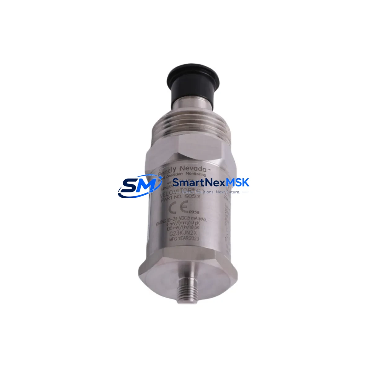
The Bently Nevada 190501-22-00-00 Velomitor CT is a high-performance piezoelectric velocity transducer engineered for continuous vibration monitoring in rotating machinery applications. As legacy Bently Nevada 3300 and 3500 Series monitoring systems approach end-of-life or face discontinued spare parts availability, the 190501-22-00-00 serves as a critical retrofit-ready replacement that enables plant engineers to maintain measurement continuity without redesigning the entire monitoring architecture.
This unit is fully compatible with Bently Nevada’s 3500/42M Proximitor/Seismic Monitor and the 3300/16 Velocity Monitor, making it an ideal drop-in solution for facilities operating turbines, compressors, pumps, motors, and gearboxes under continuous condition monitoring. The transducer outputs a standard velocity signal (mV/mm/s or mV/in/s) that integrates directly with existing signal conditioning modules and DCS historian inputs without requiring firmware changes or recalibration of the monitoring rack.
SMARTNEXMSK maintains verified stock of the 190501-22-00-00 with full 12-month warranty coverage, pre-shipment functional testing, and documentation support for IEC 61511 and API 670 compliance audits.
Upgrade Compatibility Table
| Parameter | Details |
|---|---|
| SKU / Part Number | 190501-22-00-00 |
| Brand | Bently Nevada |
| Series Compatibility | Bently Nevada 3300 Series, 3500 Series |
| Compatible Monitor Modules | 3500/42M Proximitor/Seismic Monitor, 3300/16 Velocity Monitor |
| Transducer Type | Piezoelectric Velocity (Velomitor CT) |
| Output Signal | Velocity (mV/mm/s), compatible with existing signal conditioning |
| Connector / Interface | Standard 2-pin MIL-spec connector; direct replacement wiring |
| Mounting | Stud-mount; compatible with existing machinery mounting pads |
| Installation Requirement | No rack reconfiguration required; plug-and-play retrofit |
| Communication Compatibility | Analog signal; compatible with 4–20 mA and voltage-based DCS inputs |
| Replacement Recommendation | Direct replacement for discontinued 190501-22-00-00 units |
| Commissioning Notes | Verify sensitivity calibration against 3500/42M channel configuration; confirm alarm setpoints in System 1 software |
| Warranty | 12-Month Warranty — functional testing completed prior to shipment |
Retrofit Planning for Existing Automation Systems
When planning a retrofit involving the 190501-22-00-00 Velomitor CT, the scope of work typically extends beyond the transducer itself. Engineers must evaluate the full signal chain from the field device through to the control room. In most 3500 Series installations, the transducer connects to a 3500/42M Proximitor/Seismic Monitor module seated in a 3500/05 Rack Interface Module chassis. Before swapping the transducer, confirm that the rack’s I/O terminal block wiring matches the replacement unit’s pinout — particularly the shield grounding and signal polarity.
Power supply integrity is equally critical. The 3500/15 Power Supply Module must deliver stable DC voltage within specification; a degraded power supply can introduce noise artifacts that mimic false vibration alarms after transducer replacement. Similarly, if the facility is migrating from an older 3300/16 Velocity Monitor to a 3500-series rack, the backplane slot addressing and channel configuration must be updated in the Rack Configuration Software (RCS) before the new transducer is commissioned.
For plants running System 1 Evolution condition monitoring software, the historian tag mapping for the replaced channel must be verified. If the original 190501-22-00-00 was assigned a specific machine train tag, the replacement unit should inherit the same tag to preserve trend data continuity. Alarm thresholds configured in the 3500/42M channel — including overall vibration, 1X, and 2X amplitude limits — should be documented before removal and re-entered after installation.
In facilities where the monitoring rack communicates via Modbus RTU or Ethernet/IP to a Honeywell DCS or Emerson DeltaV system, the protocol gateway configuration (often handled by a 3500/92 Communication Gateway Module) does not require changes when performing a like-for-like transducer swap. However, if the retrofit involves upgrading from a 3300-series to a 3500-series rack, the gateway module’s register map must be updated to reflect the new rack’s data structure.
Cable routing and conduit integrity should also be inspected during the retrofit. The Velomitor CT Extension Cable (typically 330130-series armored cable) connecting the transducer to the junction box must be checked for insulation degradation, especially in high-temperature or chemically aggressive environments. Replacing the transducer without inspecting the extension cable is a common source of post-retrofit signal anomalies.
Finally, for facilities using Bently Nevada TDXnet or 3500/22M Transient Data Interface modules for startup and coast-down analysis, confirm that the new transducer’s sensitivity value is correctly entered into the TDI channel configuration to ensure accurate Bode and polar plot generation during the next machine run-up.
Downtime Control During System Migration
Minimizing unplanned downtime during a Velomitor CT replacement requires a structured pre-outage preparation protocol. Before the maintenance window opens, the replacement 190501-22-00-00 should be bench-tested against a calibrated reference signal to confirm sensitivity within ±5% of the nameplate specification. This pre-shipment verification — which SMARTNEXMSK performs on every unit — eliminates the risk of discovering a defective replacement only after the original transducer has been removed from the machine.
During the outage, the recommended sequence is: (1) document all current alarm setpoints and channel configurations from the 3500/42M monitor; (2) remove the original transducer and inspect the mounting surface and stud thread condition; (3) install the replacement 190501-22-00-00 and torque to specification; (4) reconnect the extension cable and verify continuity and insulation resistance; (5) power up the monitoring rack and confirm the channel reads a valid signal in bypass mode before returning to normal monitoring.
For critical machinery where continuous monitoring cannot be interrupted, a temporary portable vibration analyzer can be deployed on the machine bearing housing to maintain surveillance during the brief period when the permanent monitoring channel is offline. This approach is particularly important for high-speed compressors and steam turbines where bearing failure progression can be rapid.
Original program logic in the DCS or safety instrumented system (SIS) does not require modification for a like-for-like transducer replacement. The 4–20 mA or voltage output from the 3500/42M monitor card remains unchanged, preserving all interlock and shutdown logic without requiring a Management of Change (MOC) review in most jurisdictions — though local safety regulations should always be confirmed with the site HSE team.
Retrofit Support FAQ
Q1: Is the 190501-22-00-00 a direct drop-in replacement for the original Bently Nevada Velomitor CT?
Yes. The 190501-22-00-00 is a direct replacement with identical connector pinout, sensitivity specification, and mounting dimensions. No modifications to the existing cable, terminal block, or monitor module configuration are required for a like-for-like swap in 3300 or 3500 Series installations.
Q2: What commissioning steps are required after installation?
After mechanical installation, verify the channel signal level in the 3500/42M Rack Configuration Software (RCS) with the machine at rest and at operating speed. Confirm that the overall vibration reading is within the expected baseline range for the machine. Re-enter any alarm setpoints that were cleared during the channel reconfiguration, and perform a functional test of the OK relay output before returning the machine to service.
Q3: How is wiring compatibility confirmed before installation?
Compare the replacement unit’s connector pinout (available in the Bently Nevada 190501 series datasheet) against the existing field wiring termination drawing. Pay particular attention to shield grounding — the Velomitor CT uses a case-grounded shield that must not be double-grounded at both the transducer and the junction box. Insulation resistance between signal conductors and shield should measure greater than 100 MΩ before powering the channel.
Q4: What does the 12-month warranty cover, and what testing is done before shipment?
Every 190501-22-00-00 unit shipped by SMARTNEXMSK undergoes pre-shipment functional testing including sensitivity verification, connector integrity check, and insulation resistance measurement. The 12-month warranty covers manufacturing defects and functional failures under normal operating conditions. Units are shipped with a test report and are eligible for warranty replacement or repair within the coverage period. Contact sales@smartnexmsk.com for warranty claims or technical support.
© 2026 SMARTNEXMSK. All rights reserved.
Original Source: https://smartnexmsk.com
Contact: sales@smartnexmsk.com | +86 18259474341


