Bently Nevada 190501-23-00-04 Retrofit-Ready Velocity Transducer for 3500 Series Control Systems
The Bently Nevada 190501-23-00-04 Velomitor CT is a high-performance piezoelectric velocity transducer engineered for continuous vibration monitoring in rotating machinery applications. As legacy installations age and original spare parts become increasingly difficult to source, this unit serves as a proven retrofit-ready replacement for facilities operating Bently Nevada 3500 Series machinery protection systems, 7200 Series proximity systems, and older ADRE-based condition monitoring platforms.
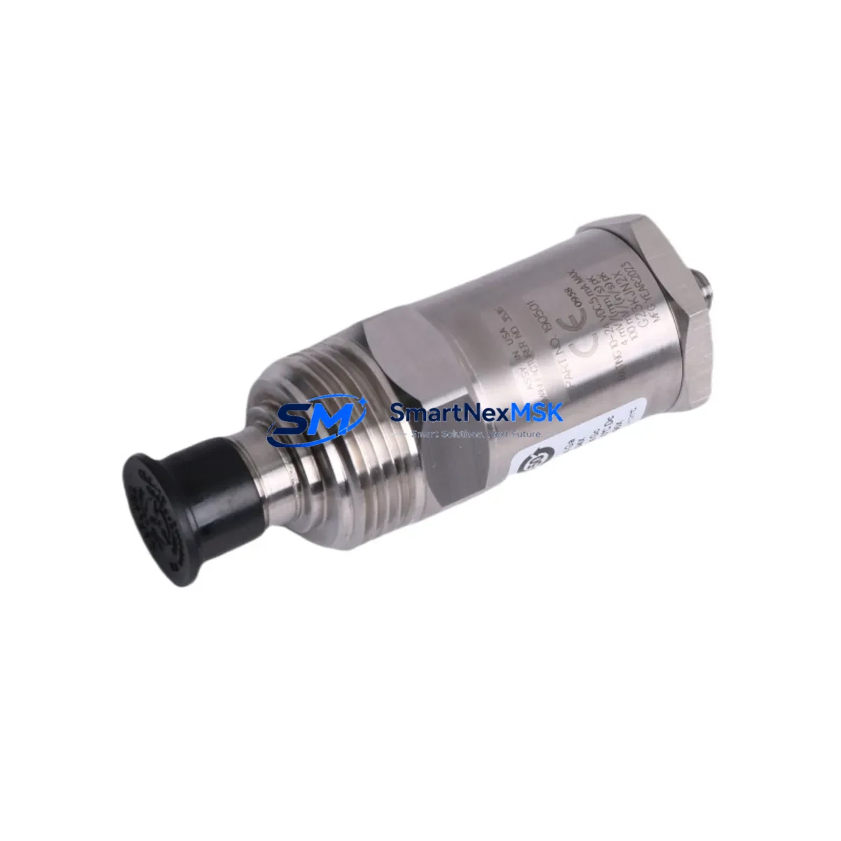
Designed to deliver flat frequency response across a wide operating range, the 190501-23-00-04 integrates directly into existing cable runs and terminal blocks without requiring modifications to the host monitor rack. Its compact stainless-steel housing and integral cable assembly make it suitable for turbine bearing housings, compressor casings, pump pedestals, and gearbox covers where space constraints and environmental exposure are primary concerns.
For plants currently running Bently Nevada 3500/42M velocity and acceleration monitor cards, the 190501-23-00-04 provides a direct signal-compatible input, preserving existing alarm setpoints, OK relay logic, and buffered output wiring to the DCS or safety instrumented system. Engineers migrating from older 7200 Series installations to the 3500 platform will find that the Velomitor CT’s output sensitivity and impedance characteristics align with the input specifications of the 3500/42M and 3500/45 position monitor cards, simplifying the transition without requiring full recalibration of the monitoring chain.
Upgrade Compatibility Table
| Parameter | 190501-23-00-04 Velomitor CT | Retrofit Notes |
|---|---|---|
| Output Sensitivity | 100 mV/in/s (4 mV/mm/s) | Compatible with 3500/42M and 3500/45 monitor inputs |
| Frequency Range | 2 Hz – 1,000 Hz (±3 dB) | Covers low-speed machinery and high-frequency bearing defects |
| Connector / Cable | Integral armored cable, MIL-C-5015 connector | Verify existing junction box connector type before installation |
| Housing Material | 316 Stainless Steel | Suitable for harsh environments; no adapter required |
| Mounting Thread | 1/4-28 UNF or M8 (confirm per order suffix) | Check existing tapped hole before ordering |
| Power Requirement | 18–30 VDC (IEPE / ICP® compatible) | Confirm barrier or driver card supply voltage |
| Communication / Signal | Analog voltage output (single-ended) | No protocol migration required; direct wiring replacement |
| Replacement Recommendation | Direct drop-in for 190501-xx-xx-xx family | Verify suffix digits for cable length and connector variant |
| Commissioning Focus | Zero-speed OK check, alarm trip test | Use Bently Nevada Rack Configuration Software (RCS) for setpoint verification |
| Warranty | 12-Month Warranty — Covered against manufacturing defects from date of shipment | |
Retrofit Planning for Existing Automation Systems
Successful integration of the 190501-23-00-04 into an aging machinery protection system requires a structured pre-installation review. Begin by auditing the existing Bently Nevada 3500 rack configuration: confirm which monitor cards are installed — typically the 3500/42M Velocity and Acceleration Monitor or the 3500/40M Proximitor/Seismic Monitor — and verify that the transducer input channel is configured for velocity (not proximity or acceleration) in the Rack Configuration Software.
Next, inspect the field wiring from the junction box to the monitor rack. The 190501-23-00-04 uses a two-conductor shielded cable; confirm that the existing cable run is intact, that the shield is grounded at one end only (typically at the rack end), and that no intermediate splices have degraded signal integrity. If the plant uses Bently Nevada 3500/20 rack power supply modules, verify that the 24 VDC transducer supply rail is within tolerance before connecting the new sensor.
For facilities that have already migrated their DCS to a modern platform — such as an Emerson DeltaV SIS or Honeywell Safety Manager — and are retaining the Bently Nevada 3500 rack as the machinery protection layer, the buffered output from the 3500/42M can be wired directly to the DCS analog input card without signal conditioning. This preserves the existing HMI trend displays and historian tags, avoiding costly graphics rework on the operator workstation.
Plants upgrading from standalone vibration switches or older Metrix ST5484E velocity transmitters to the Bently Nevada ecosystem should note that the 190501-23-00-04 requires a constant-current excitation source (IEPE-compatible), which is provided internally by the 3500/42M monitor card. If the existing field barrier or isolator was designed for a passive sensor, it must be replaced with an IEPE-compatible barrier such as the MTL 5041 or P+F KFD2-VR4 before the Velomitor CT can be powered correctly.
During rack-level commissioning, use the Bently Nevada Rack Configuration Software to confirm channel OK thresholds, full-scale range, and integration mode (velocity direct vs. integrated from acceleration). If the plant also operates Bently Nevada 3500/22M transient data interface cards or a System 1 condition monitoring server, verify that the new transducer’s channel mapping is updated in the System 1 database to maintain continuity of trend data and alarm history.
Downtime Control During System Migration
Minimizing unplanned downtime during a transducer replacement is critical in continuous-process industries such as petrochemical, power generation, and LNG. The recommended approach is a hot-standby swap procedure: with the machine at a scheduled maintenance window, bypass the OK relay output from the affected 3500/42M channel at the relay output module (3500/32 or 3500/33) before disconnecting the old transducer. This prevents a spurious trip signal from propagating to the ESD system or DCS interlock logic while the channel is open-circuit.
Once the 190501-23-00-04 is mechanically installed and the cable is terminated at the junction box, restore the channel and observe the OK LED on the 3500/42M front panel. A steady green OK indication confirms that the transducer bias voltage is within the acceptable window (typically −2 VDC to −18 VDC for IEPE sensors on the 3500 platform). Record the bias voltage reading in the maintenance log before re-enabling the relay output.
For plants where a full rack replacement is planned — for example, migrating from a legacy Bently Nevada 3300 Series rack to the current 3500 Series — the 190501-23-00-04 can be installed on the new rack while the old rack remains in service, allowing parallel monitoring during the cutover period. This approach protects original program logic in the DCS, preserves HMI alarm displays, and maintains communication link integrity between the machinery protection system and the plant historian, reducing the risk of data gaps in the condition monitoring record.
All units are function-tested and loop-checked prior to shipment. In-stock units are available for same-week dispatch, supporting urgent maintenance schedules and unplanned outage recovery.
Retrofit Support FAQ
Q1: Is the 190501-23-00-04 a direct replacement for other Velomitor CT suffix variants?
The 190501-23-00-04 is one configuration within the Bently Nevada 190501 Velomitor CT family. The suffix digits encode cable length, connector type, and mounting thread. Before ordering, confirm the suffix of the unit being replaced to ensure the cable length and connector match the existing installation. If the original suffix is no longer available, our technical team can advise on the closest compatible variant or provide an adapter solution.
Q2: What commissioning steps are required after installation?
After mechanical installation and cable termination, power up the 3500/42M monitor card and verify the channel OK status via the front-panel LED and the Rack Configuration Software. Perform a static calibration check by comparing the bias voltage reading against the transducer datasheet specification. Then conduct a bump test or use a calibrated shaker to verify the sensitivity and frequency response before returning the machine to service.
Q3: Can this transducer be used with third-party vibration monitors?
Yes. The 190501-23-00-04 is an IEPE-compatible (ICP®) velocity transducer and can be used with any monitor or data acquisition system that provides a constant-current excitation source in the 2–20 mA range. Compatibility has been verified with Emerson AMS 2140, SKF Microlog, and National Instruments DAQ platforms. Confirm the input impedance and excitation current specification of the target system before installation.
Q4: What does the 12-month warranty cover?
The 12-month warranty covers manufacturing defects in materials and workmanship from the date of shipment. It includes free replacement or repair of any unit found to be defective under normal operating conditions. The warranty does not cover damage resulting from improper installation, mechanical impact, chemical exposure beyond the rated specification, or operation outside the specified supply voltage range. All warranty claims are processed within 5 business days of receipt of the returned unit.
© 2026 SMARTNEXMSK. All rights reserved.
Original Source: https://smartnexmsk.com
Contact: sales@smartnexmsk.com | +86 18259474341


